For product context, see the fan blade mould page.
When an injection-molded fan blade wobbles on an arbor or produces an unstable balance result, the visible motion does not identify the cause. Hub bore geometry, datum choice, fixture fit, blade shape, material distribution, molding variation, trimming and test setup can all influence the reading. A useful T1 review separates geometric runout from mass imbalance and then reconnects both to the assembled fan requirement. Record the exact part and mold revision, resin grade and lot, cavity, shot sequence, conditioning time, arbor and fixture revision, measurement method, orientation, speed and mating-component state. This is a generic engineering example, not a customer case or a universal balance specification.
1. Separate runout from imbalance
Runout is a geometric measurement relative to a defined axis or datum. Imbalance describes how mass is distributed around the rotation axis and is assessed through a balancing process. A fan blade can show hub or rim runout without failing the approved balance requirement, and it can be geometrically repeatable while still carrying an unacceptable residual imbalance. Do not replace one result with the other.
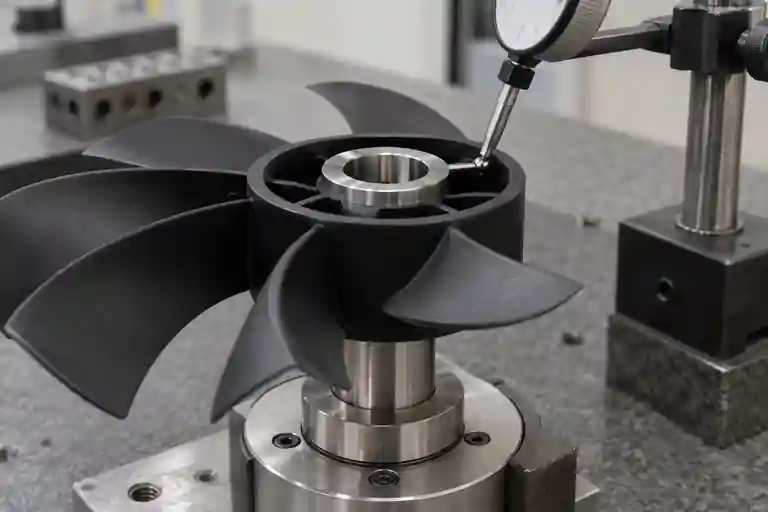
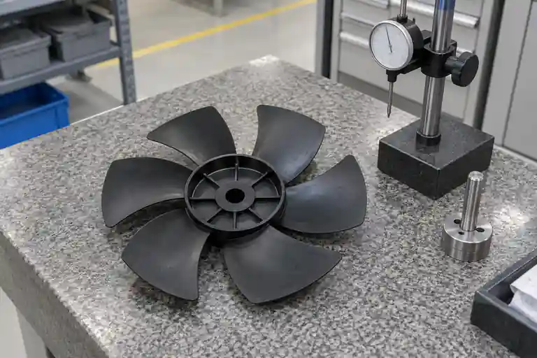
Map the inspected features before measuring: hub bore, hub face, blade tip circle, shroud if present, and the mounting interface. State whether the result is radial or axial, where the probe contacts, and how the part is restrained. Report the balance configuration separately, including the arbor, correction plane or planes, orientation convention and whether inserts, clips or other production components are installed.
2. Control the datum, arbor and mounting repeatability
Clean the hub and arbor, verify the correct revision, and inspect for gate remnants, flash, contamination or local damage at the mounting interface. Use the specified seating direction and retention method without forcing the hub. Rotate, remove and remount the same sample to determine whether the reading follows the part or the setup.
A loose fit can allow the part to shift; an excessive interference or uneven clamp can deform a plastic hub. Arbor error, fixture eccentricity and probe alignment can also be added to the part result. Keep a qualified reference artifact or master part where the inspection plan requires one, and record fixture verification independently from the sample result.
3. Review hub and blade geometry as one mass system
Check hub wall thickness, ribs, blade-root transitions, gate vestige, inserts and any post-mold trimming. Small repeated differences distributed across several blades can matter even when no single blade looks visibly defective. Compare cavity patterns and sample orientation rather than grinding or trimming an unidentified heavy location.
Autodesk explains that material orientation affects shrinkage, warpage and impact direction, and that orientation depends on flow, thickness, geometry, material and fillers. See the Autodesk material-orientation result guidance. Its guidance also identifies molding conditions, gate location and part thickness as ways to influence orientation-related deflection. See Autodesk guidance on orientation-related warpage. These sources support a hypothesis review; they do not prove the cause of a specific fan blade.
4. Keep molding and handling evidence traceable
Retain sample identity by resin lot, cavity and shot sequence. Preserve the controlled machine record, material preparation, cooling and ejection observations, trimming status and time from molding to measurement. Check whether hub seating or blade shape changes after conditioning, stacking, transport or assembly.
When a process change improves one reading, inspect the complete part again for fill, dimensions, blade profile, hub strength, appearance and new defects. When a geometry or gate change is proposed, compare the predicted direction and sensitive regions with traceable molded evidence. One improved balance number is not enough to approve a steel or process change.
5. Define the balance requirement from the real rotor configuration
ISO 21940-11 establishes procedures and unbalance tolerances for rotors with rigid behaviour, including permissible residual unbalance, correction planes and balancing-process errors. See ISO 21940-11:2016. The project must still define whether the molded fan blade behaves as the assessed rotor, the applicable balance quality, operating speed and assembled configuration. Do not copy a generic grade or tolerance without engineering approval.
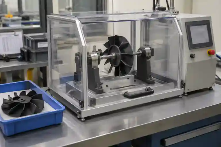
ISO 21940-21 covers the description and evaluation of hard- and soft-bearing balancing machines. See ISO 21940-21:2022. This reinforces the need to treat machine capability and setup as controlled inputs, not as invisible assumptions behind a single result.
6. Verify safely and close T1 with repeatable evidence
Rotational testing must use the approved machine, guarding, speed range and operating procedure. ISO 21940-23 addresses enclosures and other protective measures for balancing-machine measuring stations. See ISO 21940-23:2012. It does not replace the site risk assessment or equipment instructions.
| Review item | Controlled input | Closing question | Evidence |
|---|---|---|---|
| Datum and runout | Drawing, arbor, probe point and mounting method | Does the reading repeat after remounting? | Setup photos and repeated readings |
| Blade geometry | Blade profile, tip circle and hub-face references | Is wobble local, cavity-related or setup-related? | Dimensional map by sample and cavity |
| Mass distribution | Complete production configuration | Where is residual imbalance observed and under which setup? | Guarded balance report and retained samples |
| Molding hypothesis | Material, gate, packing, cooling and trimming history | Which mechanism matches the direction and repeatability? | Versioned trial plan and process evidence |
| Assembly verification | Production mating parts and approved operating requirement | Does the corrected rotor meet the project requirement without new defects? | Traceable retest and assembly record |
This table is an editorial project-control suggestion, not an industry standard. Related scope is available in the appliance mould category, mold review service and injection molding service. For corrective-action control, see the T1 corrective-action and retest checklist. To review a specific fan blade, submit the CAD, controlled drawing, resin specification, sample map, arbor definition, balance requirement and traceable trial record. No fixed runout, residual imbalance, vibration, speed, process setting, correction result or delivery outcome is promised.
Frequently asked questions
Does visible wobble prove the fan blade is imbalanced?
No. Wobble may reflect runout, mounting error, fixture error or part deformation. Imbalance requires a controlled balance measurement in the approved rotor configuration.
Can hub runout be checked on any convenient pin?
Not reliably. The arbor fit, axis, seating face, retention method and probe point all influence the result. Use the drawing and approved inspection plan.
Should material be removed from the heaviest-looking blade?
No. Correction location and method must follow the released design and balancing plan. Uncontrolled trimming can damage the blade, change strength and hide an unstable molding condition.
Is one balance value enough to approve T1?
No. Confirm mounting repeatability, sample and cavity traceability, dimensional condition, full-part quality and the project-defined assembled requirement.
What should be supplied for a T1 review?
Provide released CAD and drawings, datums and runout definitions, resin grade, sample and cavity IDs, molding records, arbor and fixture revisions, mating components, balance configuration, operating speed range and approved acceptance criteria.