For product context, see the battery case mould page.
When an injection-molded battery enclosure leaks during T1 testing, the visible water or pressure loss does not identify the cause by itself. Sealing-land shape, gasket-groove geometry, local flash, insert height, lid stiffness, fastener sequence, gasket condition, fixture loading and molding variation can all influence the result. A useful review separates free-state part geometry from the assembled sealing system and then reconnects both to the released product test. Record the exact mold and part revision, resin grade and lot, cavity, shot sequence, conditioning time, measurement datum, fixture revision, gasket lot, lid revision, fastener method and leak-test configuration. This is a generic engineering example, not a customer case or a universal sealing specification.
1. Define the sealing system before measuring it
Map the complete seal path: groove floor and walls, sealing land, corners, bosses, inserts, lid interface, gasket joint if present, fasteners and test port. Mark which features belong to the molded base, lid, gasket and assembly fixture. A leak is a system result; it should not automatically be assigned to one molded half.
State the project-defined datum scheme and the functional features to be inspected. ISO 1101 defines the symbol language and interpretation rules for geometrical specifications. See ISO 1101:2017. The drawing and inspection plan must still identify the actual datums, toleranced features, restraint condition and measurement method for this enclosure.
2. Separate free-state geometry from clamped assembly geometry
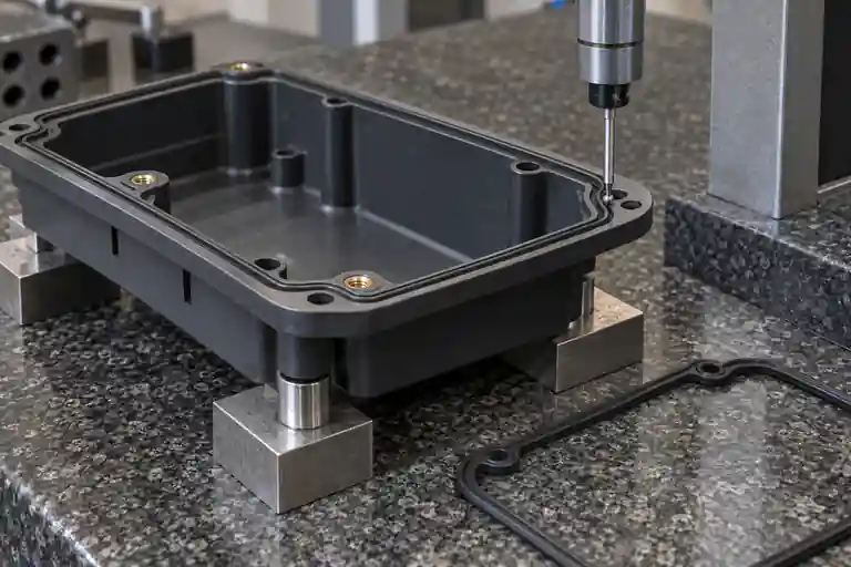
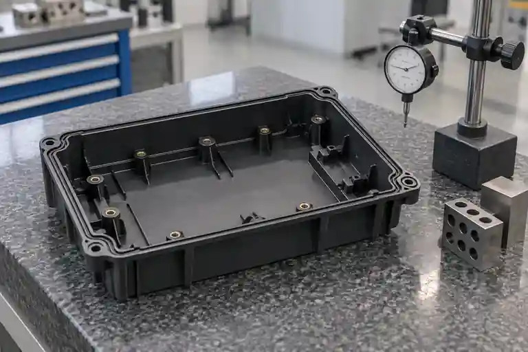
Measure the enclosure in the agreed free-state condition using repeatable supports that do not force the flange flat. Record the probe path, support locations, orientation, conditioning state and whether inserts or other production components are present. Repeat after removing and replacing the sample to expose setup variation.
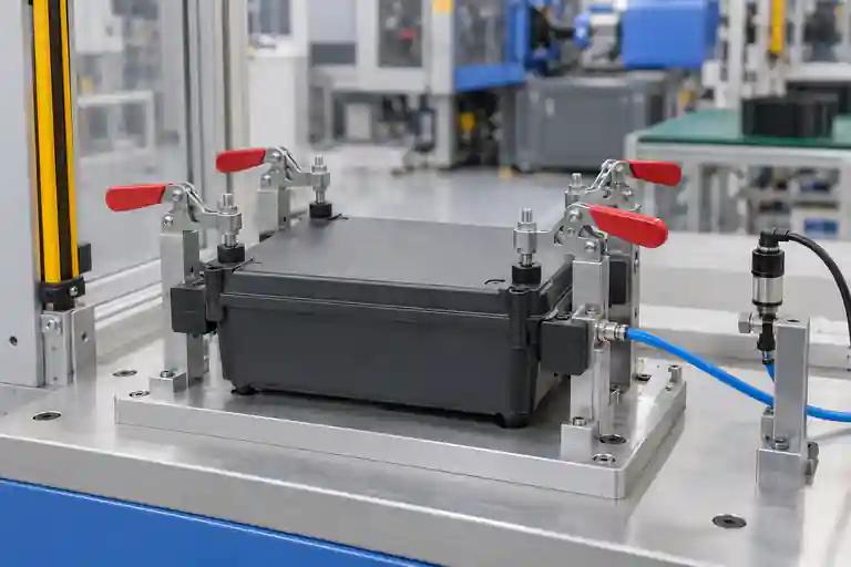
Then evaluate the approved assembled configuration. The lid, gasket and fasteners can redistribute the flange shape, while an uneven fixture or clamp sequence can create a false improvement or a false failure. Do not compare an unrestrained scan with a heavily clamped leak test as if they represent the same boundary condition.
3. Inspect the groove, sealing land and local discontinuities
Check groove width, depth and continuity only where the drawing defines them, and inspect the sealing land for flash, gate vestige, ejector witness, weld-related surface change, contamination, damage or insert protrusion. Pay particular attention to corners, fastener transitions and regions where wall thickness or rib layout changes near the seal path.
ISO 20457:2026 provides a plastics-specific framework for geometrical and dimensional tolerances and acceptance conditions, recognizing effects such as shrinkage, warpage, material behaviour, geometry and processing. See ISO 20457:2026. It does not supply a universal gasket-groove tolerance for every enclosure; functional requirements and achievable molding capability must be agreed in the product definition data set.
4. Connect the distortion pattern to molding evidence
Preserve sample identity by resin lot, cavity and shot sequence. Retain material preparation, fill and pack records, mold-temperature and cooling evidence, ejection observations, insert condition and the time from molding to measurement. Compare the direction of flange movement with gate layout, thickness transitions, ribs, bosses and cooling asymmetry.
Autodesk describes packing profiles, thickness variation and mold inserts as factors that can influence differential-shrinkage warpage, and advises rerunning the relevant analyses after design or process changes. See Autodesk guidance on differential-shrinkage warpage. This supports hypothesis testing; simulation or one improved trial does not prove the root cause without traceable molded evidence.
5. Control gasket, lid, fasteners and leak-test setup
Use the released gasket material, section, joint condition and lot. Verify the lid revision, inserts, fasteners, tightening tool, sequence and any specified dwell or conditioning. Record fixture contacts and make sure the fixture does not bypass the production load path. Keep leak-test pressure, medium, stabilization time, measurement duration and equipment verification under the approved project plan.
IEC 60529 classifies degrees of protection provided by electrical-equipment enclosures. See IEC 60529 consolidated version. Its scope does not mean that an empty molded half, an improvised pressure test or a generic water spray proves an IP rating. Product applicability, complete assembly, test method and acceptance criteria require the released specification and qualified test plan.
6. Close T1 with matched dimensional and functional evidence
| Review item | Controlled input | Closing question | Evidence |
|---|---|---|---|
| Free-state flange | Datum, supports, orientation and conditioning | Does the shape repeat without forced restraint? | Repeated dimensional map by cavity |
| Groove and land | Drawing-defined features and probe path | Where is continuity or local geometry interrupted? | Traceable profile and visual record |
| Assembly load | Lid, gasket, fasteners and sequence | Is compression distributed through the production load path? | Assembly record and witness review |
| Molding hypothesis | Material, gate, pack, cooling and ejection history | Which mechanism matches direction and cavity pattern? | Versioned trial plan and process evidence |
| Leak verification | Released assembly and approved test method | Does the corrected assembly meet the project requirement without new defects? | Qualified retest report and retained samples |
This table is an editorial project-control suggestion, not an industry standard. Related scope is available in the custom mould category, mold review service and injection molding service. For corrective-action control, see the T1 corrective-action and retest checklist. To review a specific enclosure, submit the CAD, controlled drawings, resin specification, sample map, gasket and lid revisions, fastener plan, dimensional results and approved leak-test requirement. No fixed flatness, groove dimension, gasket compression, torque, pressure, leak rate, IP rating, process setting, correction result or delivery outcome is promised.
Frequently asked questions
Does a failed leak test prove the molded base is warped?
No. The base may contribute, but the lid, gasket, fasteners, inserts, fixture and test setup can also affect the result. Review the complete sealing system.
Should the flange be clamped flat before dimensional measurement?
Only if the released inspection plan defines that restraint. Free-state and restrained measurements answer different questions and must be reported separately.
Can a passing pressure test be called an IP rating?
No. An IP classification requires the applicable complete enclosure, specified method and approved criteria. A development leak test is not automatically equivalent.
Is one passing sample enough to approve T1?
No. Confirm repeatability across the approved sample plan, cavity and conditioning state, and check dimensional, assembly and functional evidence together.
What should be supplied for a T1 review?
Provide released CAD and drawings, datum and restraint definitions, resin grade, sample and cavity IDs, molding records, groove and flange results, lid and gasket revisions, insert and fastener details, fixture revision, test method and approved acceptance criteria.