For product context, see the automotive bumper mold page.
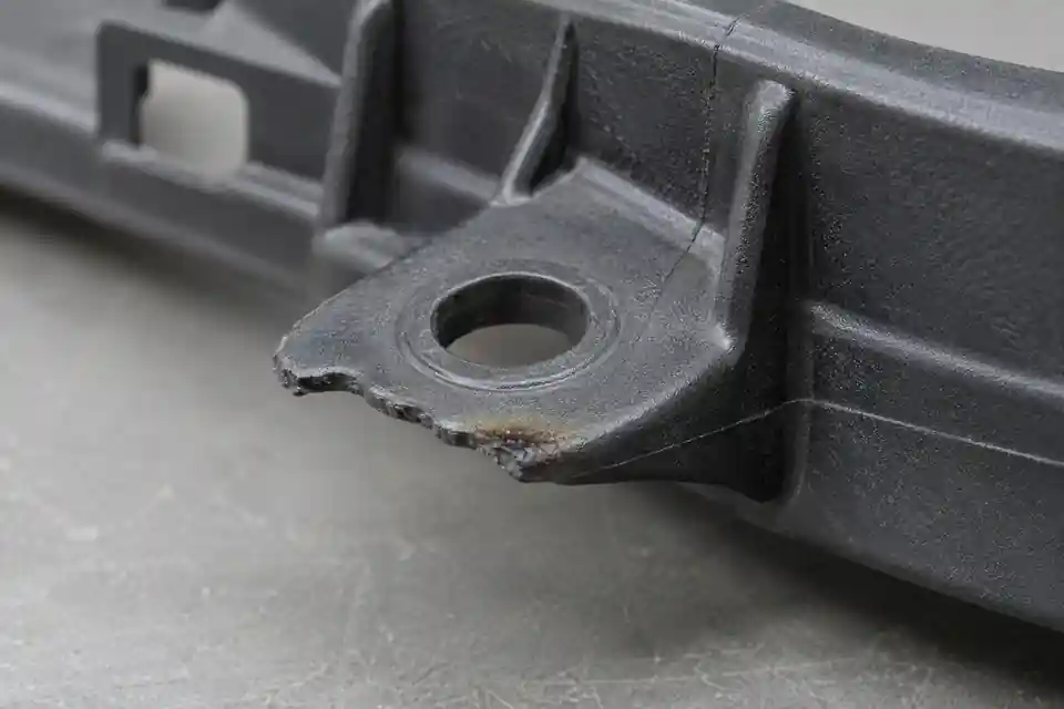
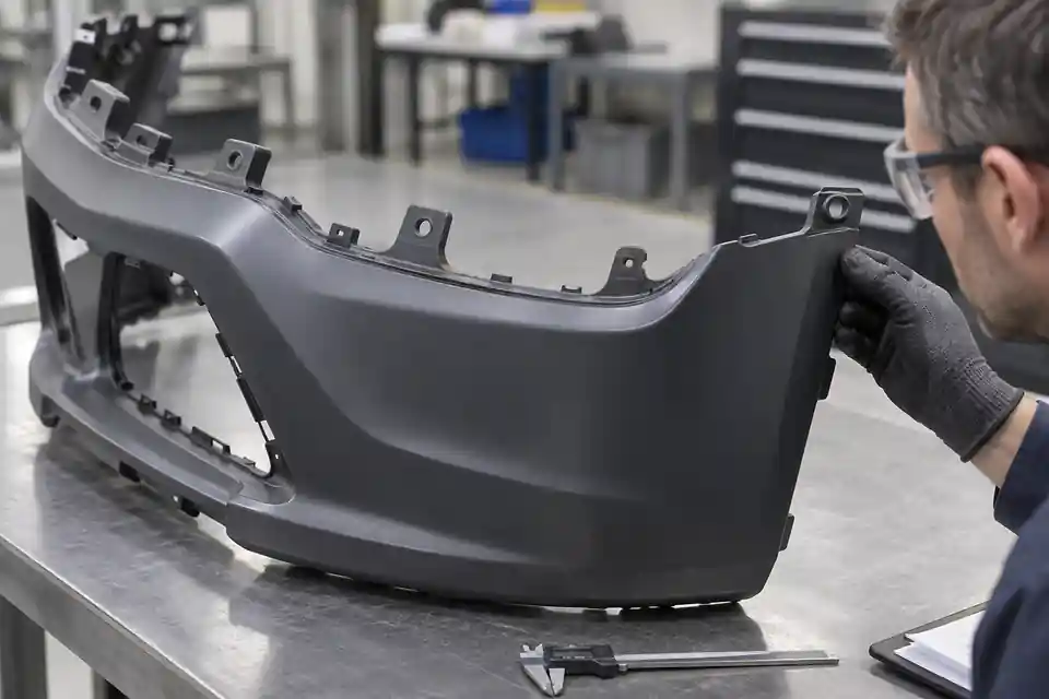
An incomplete edge or dark mark on a bumper mounting tab is a symptom, not a root-cause verdict. First separate an actual short shot from trimming damage, flash removal, handling damage or a discolored but fully formed tab. Record the bumper revision, exact location, cavity or tool position, material grade and lot, sample sequence and molding record. This article uses a generic mounting-tab scenario; it is not a customer case or a fixed process recipe.
1. Confirm the symptom and its repeatability
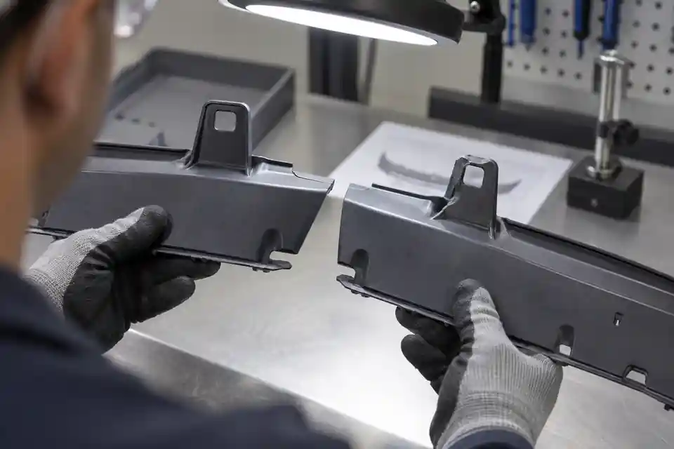
Mark every affected tab on the CAD and on the physical part. Photograph the front and back under consistent lighting, then compare the same tab across consecutive samples and other cavities or tool positions. Check whether the hole, rib, tab edge and adjacent flange are fully formed. A single damaged sample after handling should not be treated as the same evidence as a repeatable incomplete fill at one flow end.
Autodesk defines a short shot as incomplete cavity filling. Its troubleshooting guide lists flow restriction, hesitation, long or complex flow paths, inadequate venting, temperature, material delivery and machine condition among possible causes. The defect location alone is insufficient to distinguish among them. See Autodesk short-shot troubleshooting.
2. Do not treat every dark mark as trapped-air burning
A dark mark near the tab can be consistent with compressed trapped air, but it can also be associated with material degradation or excessive thermal and shear history. Autodesk's burn-mark guidance separates trapped-air heating from degradation related to melt temperature, residence time, injection speed, screw or runner conditions. Before changing steel, compare the mark's exact position, surface appearance and repeatability with the molding and material records. See Autodesk burn-mark troubleshooting.
The review should therefore keep two hypotheses open: incomplete filling and local discoloration. A tab can show one, both or neither. Increasing pressure, speed or temperature without diagnosis may move the defect or create another one.
3. Map the fill end, converging fronts and air escape
Autodesk explains that air traps can form where flow fronts converge or where a flow front reaches a cavity wall, especially at the ends of flow paths when venting is inadequate. Severe compression can contribute to burning; less severe trapped air can contribute to short shots or other surface blemishes. Use fill-time and air-trap results together where simulation is available, and compare them with actual progressive-fill evidence. See the Autodesk air-trap result guide.
Unbalanced flow means some paths fill before others. Autodesk notes that it can contribute to short shots, air traps, extra weld lines, flash and warpage. For a bumper flange, review the gate-to-tab path, thickness transitions, ribs, holes and nearby features together rather than examining the tab in isolation. See Autodesk guidance on unbalanced flow.
4. Review tab geometry and mold access before steel correction
The mounting tab may be locally thin, interrupted by a hole, supported by ribs or connected through a sharp thickness transition. Review whether the flow must split around the hole, hesitate at a thin section or finish in an area that is difficult to vent. Also check parting-line access, shutoff condition, ejector contact and whether a proposed vent or insert remains maintainable.
Protolabs lists thin walls, long flow paths and poor gate location as common design contributors to short shots, while recommending review of wall thickness, flow paths and gate placement. This is a design checklist, not a universal correction. See the Protolabs injection-molding guide.
5. Use controlled T1 evidence, not one acceptable sample
For T1 or a corrective trial, link every sample to the material lot, cavity or tool position, shot sequence and controlled process record. If a progressive-fill study is used, define its purpose and retain the sequence instead of mixing those samples with acceptance parts. Photograph the same tab location at each relevant condition and record whether the geometry is complete and whether discoloration appears.
Do not approve a correction only because one tab fills once. Confirm the project-defined appearance, assembly, retention and dimensional requirements on a controlled sample set. Any process or steel change should be evaluated for its effect on the rest of the bumper, not just the visible tab.
6. Evidence to close before correction approval
| Review item | Required input | Question to close | Evidence |
|---|---|---|---|
| Symptom identification | Marked photos and controlled sample | Short shot, discoloration or handling damage? | Agreed defect map |
| Repeatability | Cavity/tool position and shot sequence | Is the symptom stable or intermittent? | Traceable sample record |
| Fill and air | Gate path, fill end and vent access | Where do flow and air finish? | Simulation or progressive-fill comparison |
| Geometry | Tab, hole, ribs and thickness transitions | Is the local path restricted or hesitant? | Controlled CAD review |
| Verification | Appearance, assembly and dimensions | Did the correction meet project criteria without new defects? | Versioned T1 result |
This table is an editorial project-control suggestion, not an industry standard. Related context is available on the automotive mold category, mold review service and injection molding service. For trial closure, see the T1 corrective-action and retest checklist. To review a specific bumper, submit the CAD, resin specification, marked photos and traceable trial record. No fixed vent size, process setting, correction result or delivery outcome is promised.
Frequently asked questions
Does a black mark prove that trapped air caused the defect?
No. Trapped-air compression is one possible cause, while material degradation and excessive thermal or shear history can also create dark marks. Compare location and process evidence.
Should injection pressure be increased when a tab is short?
Not automatically. First check material delivery, flow restriction, hesitation, temperature, venting, gate path and machine condition. A parameter change can create a different defect.
Is adding a vent always the correct steel change?
No. Confirm where air is trapped, whether the location can be vented safely and whether the proposed feature is accessible and maintainable.
Can trimming make an incompletely filled mounting tab acceptable?
Trimming cannot restore missing molded geometry. Acceptance depends on project-defined dimensional, assembly, retention and appearance requirements.
What should be supplied for a tooling review?
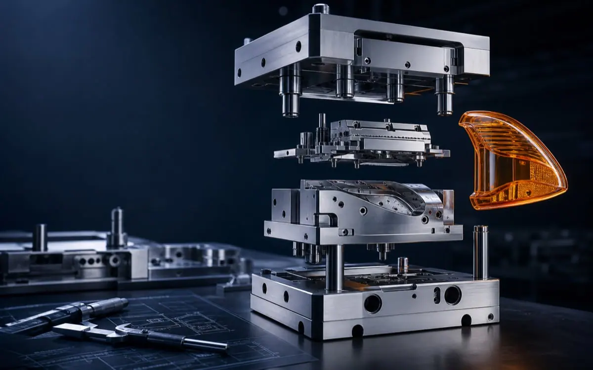
Provide CAD data showing the mold in its open and assembled states, exact material information, marked photos, cavity or tool-position identity, shot sequence, controlled process records and the project acceptance criteria.