For product context, see the automotive air-duct mold page.
When an injection-molded air duct rocks on a checking fixture, leaves a flange gap or forces one clip away from its mating hole, the visible offset is only the symptom. The review must separate free-state part shape, datum setup, fixture influence, assembly load and mold/process variation. Record the exact part revision, resin grade and lot, cavity or tool position, shot sequence, conditioning time, measurement method and mating-part revision. This article uses a generic air-duct scenario; it is not a customer case and does not prescribe a universal process setting.
1. Define the defect in assembly terms
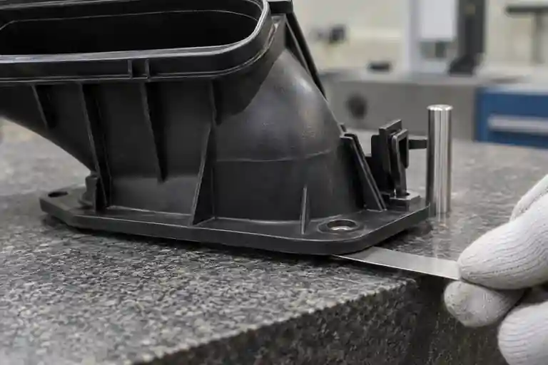
Do not use “warped” as the only inspection result. Mark the flange segment that lifts, the clip that misses, the direction of offset and the assembly consequence. Confirm whether the duct fails to seat, needs excessive force, creates a seal concern, stresses a clip or only shows a free-state deviation that disappears within the approved assembly load.
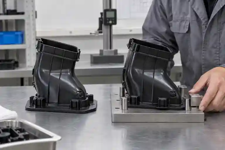
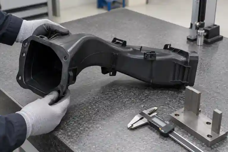
Photograph the same datums and viewing direction for every sample. A part that changes shape when placed on an uncontrolled bench cannot be compared with one restrained by a checking fixture. The drawing or project inspection plan should state which datums locate the part, where restraint is allowed and whether the reported value is free-state, fixture-state or assembled-state.
2. Separate datum error, fixture force and actual part deflection
Before changing steel, verify that the fixture is clean, stable and matched to the correct revision. Locate the duct in the specified sequence and use only the approved clamps or contact force. Check for flash, gate remnants or debris under a datum pad. Then repeat the measurement after removing and reloading the same sample.
Use a flatness or profile method that matches the drawing rather than inventing a single “gap” number. For clip position, define the inspected feature and direction: hook center, lead-in face, retention face or the mating window may give different conclusions. A clip can appear misaligned because the flange has rotated, because the clip itself is displaced, or because the mating component or fixture datum is wrong.
3. Review wall, ribs, transitions and local stiffness together
An air duct often combines curved thin walls, broad sealing flanges, ribs, bosses and snap features. These regions cool and shrink differently. Review abrupt thickness changes, heavy rib intersections, asymmetric rib patterns, large unsupported flange spans and sharp transitions near clips. The objective is not to make every region thick; it is to understand where stiffness and shrinkage are unbalanced.
Autodesk explains that differential shrinkage between part regions can drive warpage, and that adjacent thickness differences can create different volumetric shrinkage. Its deflection result can be measured against an anchor plane or a best-fit plane, which illustrates why the reference definition matters. See Autodesk differential-shrinkage deflection guidance.
4. Compare cooling, shrinkage and orientation hypotheses
Do not assume that one mechanism explains every flange lift. Autodesk groups warpage contributors into differential cooling, differential shrinkage, orientation effects and corner effects. Comparing the combined deflection with isolated-cause plots can help identify which mechanism deserves further investigation. See the Autodesk warp-cause review tutorial.
Non-uniform cooling is one possible driver. Autodesk notes that temperature differences through or across the part can produce uneven shrinkage and warpage, and recommends investigating hot spots and cooling-channel relationships. See Autodesk guidance on non-uniform cooling.
Simulation is a hypothesis tool, not acceptance evidence by itself. Use the actual resin data, mold layout and process window where available, then compare predicted displacement direction and sensitive regions with traceable samples.
5. Keep molding, handling and conditioning evidence traceable
For a T1 comparison, identify every sample by material lot, cavity or tool position and shot sequence. Retain the controlled process record, cooling and ejection observations, and the time between molding and measurement. Keep hot parts, trimmed parts, packaged parts and conditioned parts from being mixed without labels.
Check whether deformation appears immediately at ejection, develops during room-temperature conditioning, or changes after stacking, transport or assembly. This does not prove a cause, but it narrows the investigation. Any process change must be assessed across the complete duct for fill, appearance, dimensions, clip performance and new defects; a single improved flange point is not sufficient.
6. Close the correction with part and assembly evidence
| Review item | Input to control | Question to close | Evidence |
|---|---|---|---|
| Datum setup | Drawing, fixture revision and loading sequence | Is the result repeatable after reload? | Setup photos and repeated readings |
| Free-state shape | Defined reference and measurement points | Where and in which direction does the duct deflect? | Profile or point map |
| Clip alignment | Clip feature and mating interface | Is offset local or caused by flange rotation? | Fixture and mating-part check |
| Root-cause hypothesis | Geometry, cooling, shrinkage and orientation review | Which mechanism matches the observed direction and timing? | Versioned analysis and trial plan |
| Verification | Project appearance, seal, retention and assembly criteria | Did the change solve the issue without creating another one? | Traceable T1/retest package |
This table is an editorial project-control suggestion, not an industry standard. Related scope is available in the automotive mold category, mold review service and injection molding service. For corrective-action control, see the T1 corrective-action and retest checklist. To review a specific duct, submit the CAD, drawing, resin specification, marked photos, fixture definition and traceable trial record. No fixed warpage allowance, clamp force, cooling layout, process setting, correction result or delivery outcome is promised.
Frequently asked questions
Does a flange gap prove that the mold steel is wrong?
No. First verify part revision, datums, fixture condition, loading method, resin, sample history and repeatability. Steel geometry is one hypothesis, not the first automatic conclusion.
Should a warped duct be forced flat during inspection?
Only if the drawing or approved inspection plan defines that restraint and force. Otherwise the measurement may hide the free-state condition or create a result that cannot be repeated.
Can a clip be corrected without reviewing the flange?
Not reliably. Clip position may be affected by local geometry, flange rotation and overall duct deflection. Review the complete datum chain and mating interface before changing the clip alone.
Is simulation enough to approve a correction?
No. Simulation can compare mechanisms and sensitivities, but approval should use traceable molded samples and project-defined dimensional, sealing, retention and assembly checks.
What should be supplied for a T1 review?
Provide open and assembled CAD, the controlled drawing and datums, resin grade, sample IDs, cavity or tool position, molding records, measurement method, fixture revision, mating-part revision and acceptance criteria.