For product context, see the syringe mould page.
An injection-molded syringe barrel can look acceptable while its Luer connection still shows unstable engagement or leakage during an approved test. The observed result may involve the molded tip axis, taper or thread geometry, parting-line flash, resin or process variation, the reference connector, assembly method, conditioning, fixture alignment or the test procedure. A useful T1 review separates molded-part evidence from connector assembly and functional-test evidence before changing steel. Record the released CAD and drawing revision, connector type, material and lot, cavity, molding conditions, conditioning state, reference-connector identity, assembly method, fixture and test procedure. This is a generic engineering framework, not a customer case, medical-use instruction, certification statement or universal acceptance standard.
1. Define the released connector and functional boundary
Confirm whether the released design uses a Luer slip, Luer lock or another approved connection, and identify which features belong to the molded barrel, any separate collar and the mating reference component. Preserve the tested sample and reference connector as one traceable pair. A wet trace near the tip is evidence to investigate; it does not by itself prove that the molded taper is off-axis or that flash is the leak path.
ISO 80369-7:2021 specifies dimensions and design and functional-performance requirements for small-bore connectors used in intravascular or hypodermic applications, including examples such as syringes and needles with Luer slip or Luer lock connectors. Apply the released product specification and the edition approved for the project rather than inferring dimensions from a generic sample.
2. Inspect the molded tip from a defined datum system
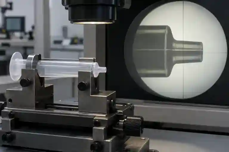
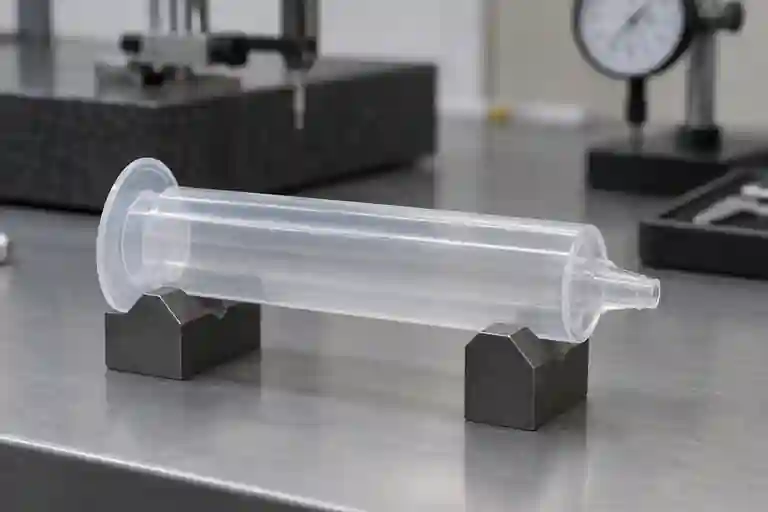
Establish the datum system and inspection state before discussing concentricity. Depending on the released definition, the relevant evidence may include the barrel axis, tip axis, taper profile, circular features, collar or thread relationship, tip opening, shoulder location and parting-line offset. Support the barrel without squeezing or bending it, and record the fixture, orientation, temperature, conditioning state, cavity and measurement program.
ISO 5459:2024 defines datums and datum systems, while ISO 1101:2017 provides the symbol language and interpretation rules for geometrical specifications. These standards help make the inspection statement unambiguous; they do not supply the product-specific tolerance. Report the actual released requirement and measurement method instead of using the word “concentricity” as a substitute for a complete specification.
3. Trace flash and axis variation to mold and process evidence
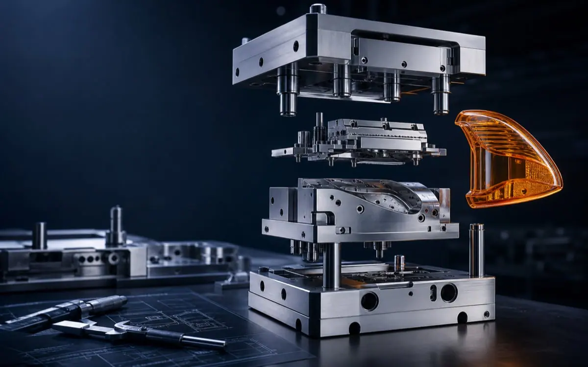
Map flash by cavity, parting-line zone and sample sequence. Review shutoff condition, inserts, venting, clamp and injection history, material condition, gate balance and ejection. A thin witness line, displaced shutoff and damaged sealing surface are different observations and should not be grouped under one defect label. Do not polish or trim the sample before documenting the as-molded condition.
ISO 20457:2026 provides a plastics-specific framework for dimensional and geometrical tolerances and explains that material, part design, tool layout, processing conditions, shrinkage and warpage influence molded-part accuracy. It also states that surface imperfections such as joint lines are outside its scope. Therefore the project must define its own released visual and functional criteria for flash while using traceable dimensional evidence for the tip geometry.
4. Separate molded geometry from connector assembly effects
Compare the molded tip first in a non-destructive inspection state, then with a controlled reference connector. Record the reference component revision and wear state, alignment, engagement method and any allowed lubrication. Cross-threading, tilted engagement, damaged reference parts, contamination or fixture side-load can change the result without proving that the mold is the only cause.
Use a controlled matrix: multiple parts from each relevant cavity, more than one verified reference connector when the plan requires it, and retained pass and fail assemblies. Change one input at a time. If the project uses a collar or another separately molded component, inspect its geometry and assembly relationship separately from the barrel tip.
5. Make leakage and connector testing repeatable
ISO 80369-20:2024 specifies common test methods used to evaluate performance requirements for connector families covered by the ISO and IEC 80369 series. ISO 7886-1:2017 covers requirements and test methods for the design of empty sterile single-use manual syringes and explicitly does not provide lot-release requirements. The ISO status page also notes a replacement is under development, so the project must verify the approved edition and applicable product scope before testing.
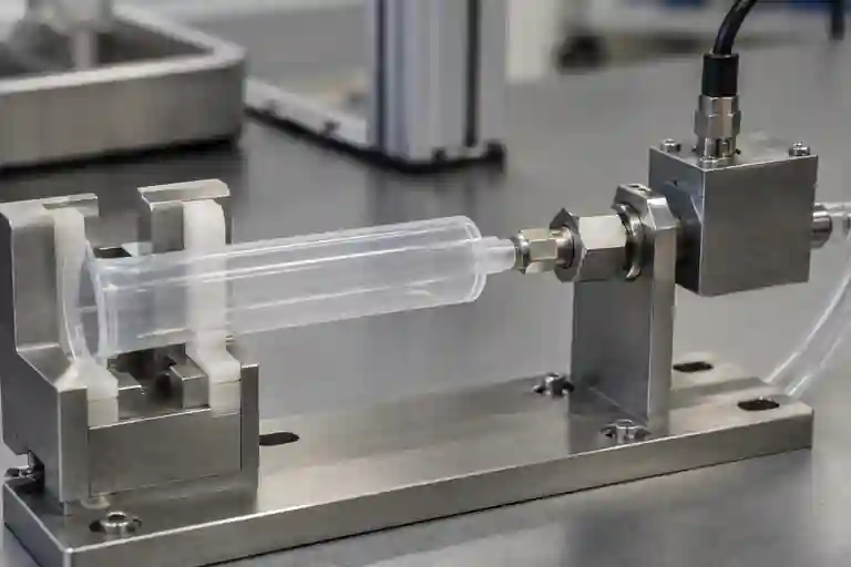
Define the test article, reference connector, assembly sequence, conditioning, medium, fixture alignment, load application, pressure or vacuum program, dwell, observation method and pass/fail rule from the approved procedure. This article does not prescribe any value. Dry or replace fixtures as required between runs, keep sample identity intact, and distinguish a connector test from a full syringe test, packaging validation, sterilization validation or production lot release.
6. Close T1 with linked molding, geometry and test evidence
| Review item | Controlled input | Closing question | Evidence |
|---|---|---|---|
| Product boundary | Released connector type and revision | Which features and tests apply to this design? | Approved CAD, drawing and test-plan references |
| Molded tip geometry | Datum setup, cavity and inspection state | Is the specified axis and taper relationship repeatable? | Measurement program, map and sample IDs |
| Parting-line flash | Zone, sample sequence and as-molded state | Is the observed flash tied to a verified tool or process mechanism? | Macro images, cavity map and molding record |
| Reference connection | Component identity, alignment and engagement | Is mating-part or assembly variation controlled? | Reference-part log and assembly traveler |
| Leakage test | Approved method, fixture and conditioning | Is the result reproducible without fixture bias? | Test record and retained paired assembly |
| Corrective action | One controlled change and retest plan | Did the change address the verified cause without creating a new risk? | Before/after evidence and approval record |
This table is an editorial project-control suggestion, not a medical-device standard. Related capabilities are listed in the medical mould category, mould service overview and injection moulding service. For corrective-action control, use the T1 corrective-action and retest checklist. To review a specific part, submit the released CAD and drawing, material and cavity records, inspection setup, reference-connector record, assembly method and approved test procedure. No fixed dimension, geometrical tolerance, flash limit, surface finish, engagement force, torque, pressure, vacuum, dwell, leakage limit, biocompatibility result, sterility result, certification, production acceptance or delivery outcome is promised.
Frequently asked questions
Does leakage prove the molded Luer tip is off-axis?
No. The result can also involve taper or thread geometry, flash, the reference connector, contamination, assembly alignment, conditioning, fixture side-load or the test procedure. Preserve the complete tested pair before assigning cause.
Can one diameter check establish Luer-tip concentricity?
No. The released specification must define the relevant feature relationship and datum system. A single diameter result does not establish an axis relationship, taper profile or connector performance.
Should flash be removed before the T1 test?
Not before the as-molded condition is documented and the approved test plan is reviewed. Unrecorded trimming destroys evidence and can hide whether the parting-line condition affects assembly or testing.
Does passing one connector test certify the syringe?
No. A T1 result is only one piece of project evidence. Product conformity, process validation, sterilization, packaging and lot release require the applicable controlled procedures and approvals.
What should be supplied for a T1 Luer-tip review?
Provide released CAD and drawings, connector type and revision, material and cavity records, molding history, datum and inspection method, tip and parting-line measurements, reference-connector identity, assembly record, approved test procedure, sample traceability and approved acceptance criteria.