For product context, see the electric kettle housing mould page.
A thin edge on an injection-molded kettle housing may be an expected parting-line witness, removable flash, mold mismatch or a feature that prevents the shell from seating. These conditions should not be grouped under one photograph and one word. A useful T1 review maps the location, separates tooling contact from process pressure, and proves whether the condition affects appearance, touch, assembly or an approved interface. Record the exact part and mold revision, resin grade and lot, cavity, shot sequence, machine, process record, trimming status, conditioning time, mating-part revision and inspection method. This is a generic engineering example, not a customer case or a universal acceptance standard.
1. Define the visible condition before naming the cause
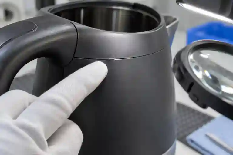
Start with a zone map of the housing perimeter. Mark where the line crosses a cosmetic face, hand-contact edge, clip, screw boss, locating datum or mating flange. Use the same lighting, camera direction and magnification for every sample. A normal parting-line witness may be visually detectable without projecting beyond the surface; flash is excess material extending from an edge or interface; mismatch is a step between surfaces formed by different mold halves.
Do not convert a photograph into an unverified dimension. If the drawing or appearance standard defines a limit, record the approved measurement method, instrument and reference. If no criterion exists, classify the observation and request project approval instead of inventing a universal flash allowance.
ISO 20457:2026 provides a plastics-specific framework for dimensional and geometrical tolerances and acceptance conditions, while its scope does not set acceptance limits for surface imperfections such as joint lines. Use it to structure dimensional requirements, then keep appearance, touch and assembly criteria project-specific. See ISO 20457:2026.
2. Check whether the line changes fit, force or touch
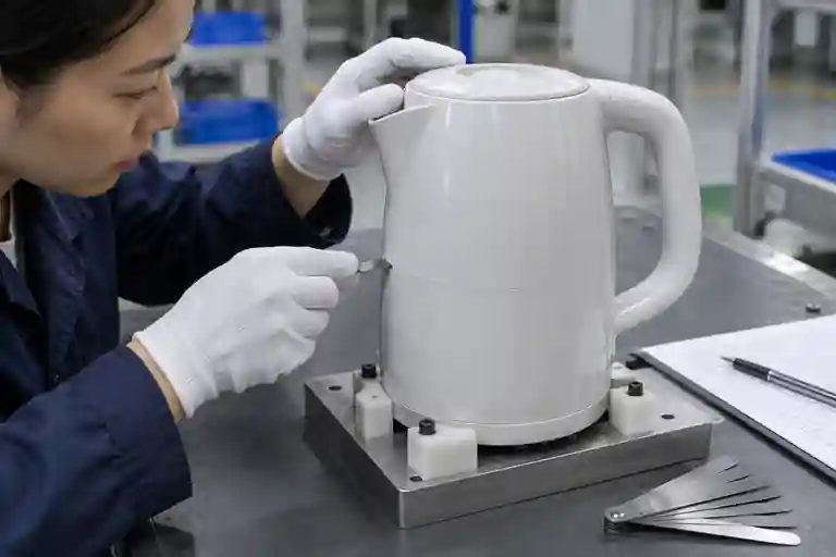
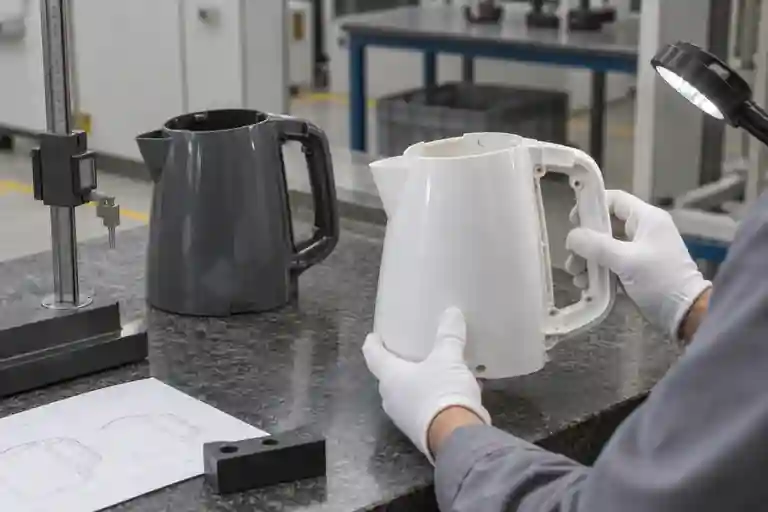
Inspect the part in three states: free, trimmed as specified, and assembled with the controlled mating components. A localized sliver may be only cosmetic in one zone but may stop a latch, hold a shell open, create a sharp hand-contact edge or distort the seam elsewhere. Record the assembly sequence and the approved load or fixture; forcing a shell closed can hide interference and produce a false pass.
Measure the assembly seam at named checkpoints tied to datums, not at whichever point looks largest in a photograph. Repeat the check after unloading and reloading the same parts. Swap only one controlled mating component at a time so that housing variation is not confused with base, lid, handle or fixture variation.
3. Inspect the parting surface and shutoffs before chasing settings
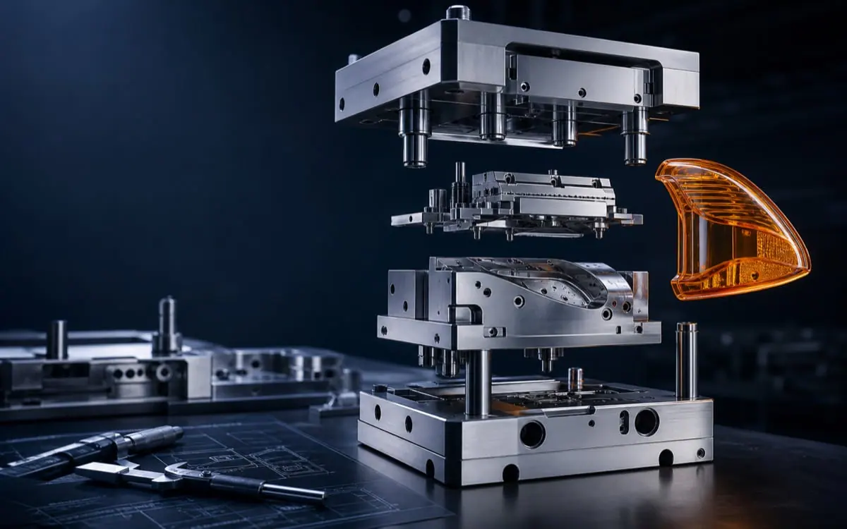
Review the mold only under the site’s approved lockout, cleaning and maintenance procedure. Look for contamination, trapped resin, damage, rolled edges, poor contact, insert or slide seating, uneven witness transfer and wear at the defect zone. Compare the location on the molded part with the corresponding parting surface, vent, insert, slide or shutoff. A repeatable cavity-specific pattern is useful evidence, but it does not by itself identify the repair.
Protolabs notes that parting-line location affects visible vestiges, function, mold cost and secondary finishing, and that mismatch along a smooth face can make the seam more obvious and increase flash risk. See Protolabs guidance on planning parting lines. Its injection-molding guide describes flash as thin excess plastic at edges or parting lines and links design review to shutoffs and parting-line placement. See the Protolabs injection molding guide.
4. Separate cavity pressure from available clamp support
Autodesk defines flash as excess polymer escaping where the mold separates and lists excessive velocity, injection velocity, packing pressure and low clamp force among common causes. See the Autodesk Moldflow flash reference. This is troubleshooting guidance, not permission to change settings without validating the complete process window.
Clamp demand is related to the cavity pressure distribution and projected area. Autodesk explains that the clamp-force result comes from pressure acting over the projected part area and recommends keeping modeled maximum demand below the machine limit with a safety margin, while noting that tool configuration can require more margin. See the Autodesk clamp-force result guidance. Do not respond by blindly maximizing clamp force: machine condition, mold protection, tool support and approved setup limits must remain controlled.
5. Run a controlled troubleshooting ladder
First preserve a known baseline and identify the affected cavities and zones. Then confirm material identity and preparation, shot consistency, transfer behavior, peak and hold-pressure records, clamp setup, mold temperature, vent condition and part-removal handling. Change one approved factor at a time, retain sample IDs and compare the complete part rather than only the original flash location.
When a lower pressure or earlier transfer reduces flash, verify that it has not created short fill, weak clips, sink, weld-line weakness, dimensional drift or unstable part weight. When maintenance improves contact, recheck the full perimeter and the assembly seam. If geometry or parting-line placement is revised, retain the released CAD, steel-change record and before/after evidence.
6. Close T1 with a traceable part-and-assembly package
| Review item | Controlled input | Closing question | Evidence |
|---|---|---|---|
| Defect map | Part, mold and cavity revision | Where does flash or mismatch repeat? | Zone photos and sample IDs |
| Tool contact | Clean parting surface, shutoffs and moving components | Does the corresponding area seat consistently? | Approved maintenance inspection record |
| Process | Material, machine and versioned setting record | Does the condition move within the approved trial plan? | Shot log and retained samples |
| Trim and touch | Released trimming method and hand-contact zones | Is the edge safe and repeatable after specified finishing? | Visual and tactile inspection record |
| Assembly | Controlled mating parts, datums and loading method | Does the shell seat without hidden interference or excess force? | Seam map and repeated fit check |
This table is an editorial project-control suggestion, not an industry standard. Related scope is available in the appliance mould category, mold review service and injection molding service. For corrective-action control, see the T1 corrective-action and retest checklist. To review a specific housing, submit the CAD, controlled drawing, resin specification, marked defect map, mating-part data and traceable trial record. No fixed flash allowance, clamp force, process setting, trim method, correction result or delivery outcome is promised.
Frequently asked questions
Is every visible parting line a flash defect?
No. A parting-line witness is expected on many molded parts. Classify whether material projects from the surface, whether there is mold-half mismatch, and whether the condition violates a project-defined cosmetic, touch or functional criterion.
Does increasing clamp force always remove flash?
No. Flash can involve tool contact, damage, contamination, cavity pressure, velocity, packing and available clamp support. Any machine change must stay within approved equipment and mold limits and be checked for side effects across the whole part.
Can trimming be used as the permanent correction?
Only if the released manufacturing plan allows it and the result is repeatable for appearance, touch, dimensions and assembly. Trimming should not conceal unresolved tool damage or an unstable molding process.
Why check the housing after assembly?
A small edge or step may change latch engagement or hold a mating shell open even when the free part looks acceptable. Assembly evidence connects the molded condition to the actual interface.
What should be supplied for a T1 review?
Provide released CAD and drawings, the parting-line and appearance definitions, resin grade, sample and cavity IDs, machine and process records, defect-zone photos, trimming status, mating-part revisions, fixture or loading method and approved acceptance criteria.