For related manufacturing scope, see the custom mould category.
When a shaft becomes tight only after an injection-molded gear housing is assembled at T1, the symptom does not identify the cause by itself. Bearing-seat size, roundness, axis relationship, housing warpage, insert position, bearing installation, fastener sequence, gear mesh, shaft straightness and test-fixture alignment can all change rotational resistance. A useful review separates the molded geometry from purchased components and assembly load, then reconnects them with traceable samples. Record the exact housing, bearing, shaft and gear revisions; resin grade and lot; mold cavity and shot sequence; conditioning time; datum setup; bearing installation method; fastener sequence; fixture version; lubrication state; and rotation-test configuration. This is a generic engineering example, not a customer case or a universal gearbox specification.
1. Freeze the functional stack and sample identity
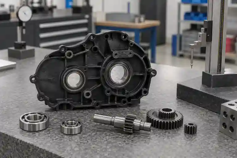
Define the complete load path before measurement: housing half or halves, bearing seats, bearings or bushings, shafts, gears, spacers, locating features, inserts, cover, gasket if present, and fasteners. A different bearing variant, shaft revision or assembly sequence can create a result that resembles a molding defect.
Link every molded housing to mold revision, cavity, resin lot and shot order. Link every bearing, shaft and gear to its controlled part number and lot. Photograph the free-state housing and components before pressing bearings or tightening the cover so installation damage is not mistaken for an as-molded condition.
2. Establish functional datums before comparing bores
The inspection plan should select datums that represent how the gearbox is located in its product and how the two housing halves locate each other. ISO 5459:2024 specifies terminology, rules and methodology for datums and datum systems. See ISO 5459:2024. It does not choose the functional datum scheme for a particular gearbox; the released drawing and inspection plan must do that.
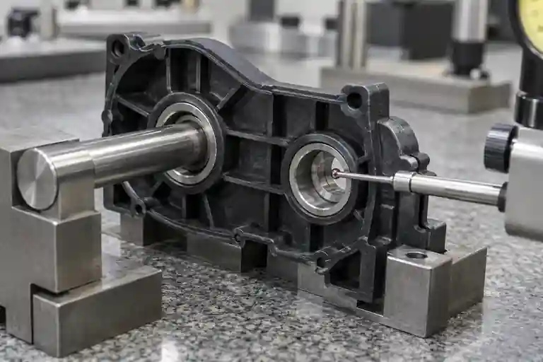
Use repeatable supports that do not pull a flexible housing into the expected shape. Record support points, clamping force or restraint condition, probe strategy, temperature and sample orientation. Remove and replace the same part, then repeat the setup to expose fixture variation before comparing cavities.
3. Separate bearing-seat size and form from axis relationship
Inspect each bearing seat for the drawing-defined size, roundness or cylindricity, lead-in condition, flash, mismatch, sink-related distortion, contamination and local damage. Then evaluate the relationship between bearing-seat axes and the functional datums. A bore can meet a size requirement yet still create a problem if its axis relationship changes; conversely, a failed rotation test does not prove that bore size is the only cause.
ISO 1101:2017 defines the symbol language and interpretation rules for geometrical specifications. See ISO 1101:2017. ISO 286-1:2010 gives the basis of the ISO code system for tolerances on linear sizes and fits. See ISO 286-1:2010. Neither source supplies a universal bearing-seat fit or coaxiality value for all plastic gear housings; the design authority must define the applicable feature specification, material condition and acceptance rule.
4. Compare free state, bearing installation and closed assembly
Measure the molded housing in the approved free-state condition first. Then repeat the relevant checks after controlled bearing or bushing installation and after the housing is assembled with released mating parts. Press force, bearing insertion depth, cover location, screw sequence and tightening method may redistribute a compliant plastic housing.
Keep these states separate in the report. A mandrel that turns freely in an open half but binds after the cover is tightened points to an assembly-dependent condition, but it still does not identify whether the cause is molded geometry, mating-part geometry, bearing installation or fastener load. Swap only one controlled component at a time and preserve the sample map.
5. Connect the geometry pattern to molding evidence
Compare results by mold cavity, shot sequence and conditioning interval. Review gate location, wall-thickness transitions, ribs, bosses, bearing-seat supports, cooling layout and ejection direction against the observed axis or housing-shape pattern. Retain material preparation, fill and pack records, mold-temperature and cooling evidence, part weight and ejection observations.
ISO 20457:2026 provides a plastics-specific framework for dimensional and geometrical tolerances and acceptance conditions, recognizing material, shrinkage, warpage, geometry and process influences. See ISO 20457:2026. Autodesk also describes packing, thickness variation and mold inserts as factors that can influence differential-shrinkage warpage. See Autodesk guidance on differential-shrinkage warpage. These sources support hypothesis testing; they do not prove a root cause without matched molded and assembly evidence.
6. Close T1 with dimensional and rotation evidence
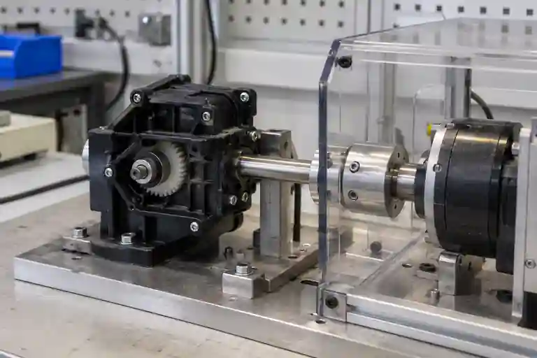
Run the approved functional check with controlled shaft, bearing, gear, lubrication, fixture and assembly state. Record the starting position, direction, speed, warm-up or cycling if specified, and whether the result is breakaway torque, running torque, angular variation, noise or another released metric. Preserve the complete curve or time history and the failure mode, not only one peak value.
| Review item | Controlled input | Closing question | Evidence |
|---|---|---|---|
| Housing setup | Datum system, support and restraint | Does the result repeat after re-fixturing? | Repeated dimensional map by cavity |
| Bearing seats | Feature specification and probe strategy | Are size, form and lead-in reviewed separately? | Bore profile and visual record |
| Axis relationship | Functional datums and mating locations | Which relationship changes across cavity or assembly state? | Axis map with setup record |
| Assembly load | Bearings, cover, fasteners and sequence | When does rotational resistance first change? | Staged assembly checks |
| Functional retest | Shaft, gears, lubrication and fixture | Does the approved sample plan pass without new defects? | Rotation curve, failure mode and retained samples |
This table is an editorial project-control suggestion, not an industry standard. Related capabilities are listed under mold review service and injection molding service. For corrective-action control, see the T1 corrective-action and retest checklist. To review a specific gear housing, submit the released CAD and drawings, datum definitions, resin and cavity map, bearing and shaft part numbers, installation method, dimensional results, assembly sequence and approved rotation criteria. No fixed bore tolerance, bearing fit, coaxiality, installation force, fastener torque, rotational torque, process setting, correction result or delivery outcome is promised.
Frequently asked questions
Does shaft binding prove the two bearing bores are misaligned?
No. Bore relationship can contribute, but shaft straightness, bearing condition, press damage, gear mesh, cover location, fastener load, lubrication and fixture alignment can create the same symptom.
Should bearings be installed before bore measurement?
Measure the state defined by the released inspection plan. Free-state molded geometry, post-installation geometry and closed-assembly behavior answer different questions and should be reported separately.
Can one reference mandrel replace a complete dimensional inspection?
No. A mandrel can reveal a functional condition, but it does not independently quantify bearing-seat size, form, axis relationship or datum error.
Is one freely rotating assembly enough to approve T1?
No. Confirm repeatability across the approved sample plan, relevant mold cavities, component lots and conditioning states, and check for new noise, wear or damage.
What should be supplied for this T1 review?
Provide released CAD and drawings, datum and restraint definitions, resin grade, cavity and sample IDs, molding records, bearing and shaft specifications, installation records, bore measurements, assembly sequence, rotation curves, fixture details and approved acceptance criteria.