For related manufacturing scope, see the custom mould category.
If a terminal is difficult to insert, backs out after assembly or prevents a TPA from closing during T1, the molded housing should not be blamed from the symptom alone. Terminal orientation, crimp deformation, locking-lance condition, cavity geometry, local flash, short shot, tool mismatch, resin shrinkage, fixture alignment and test speed can change the result. A useful review separates the molded cavity from the metal contact and the assembly process, then reconnects them with traceable samples. Record the exact housing and terminal drawing revisions, resin grade and lot, mold cavity, shot sequence, conditioning time, terminal lot, crimp tooling, wire size, insertion equipment, TPA version and force-test setup. This is a generic engineering example, not a customer case or a universal connector specification.
1. Freeze the connector configuration and sample identity
Define the connector system before measuring anything: housing, contact family, wire and crimp condition, seal if present, primary locking lance, molded retention shoulder, TPA or secondary lock, mating part and assembly direction. Mixing terminal variants or using an unreleased TPA can produce a failure that looks like a molding problem.
Keep each housing linked to mold revision, cavity, resin lot and shot order. Keep each terminal linked to forming and plating lot, crimp applicator and wire preparation. Photograph the as-received condition before insertion or pull testing so later damage is not mistaken for an original defect.
2. Establish datums and inspect the complete terminal cavity
The inspection plan should define datums that represent how the housing locates during assembly and mating. ISO 5459:2024 specifies rules and methodology for datums and datum systems. See ISO 5459:2024. It does not choose the functional datum scheme for a specific connector; that remains a drawing and product-definition decision.
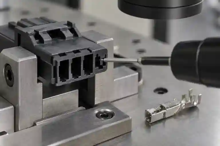
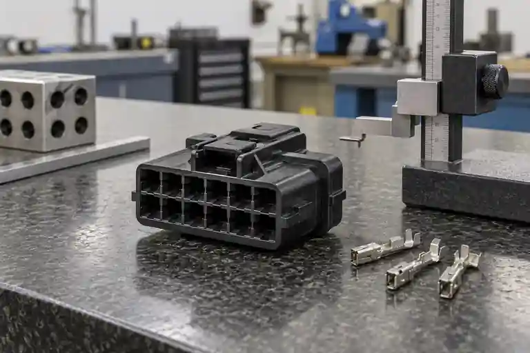
Inspect the front opening, rear lead-in, cavity pitch, guiding walls, terminal stops, locking shoulder and TPA path as one functional chain. Use a repeatable fixture that does not squeeze a flexible housing into shape. Repeat the setup after removing and replacing the sample, and compare cavities without losing their identity.
ISO 20457:2026 provides a plastics-specific framework for dimensional and geometrical tolerances and acceptance conditions, recognizing material, shrinkage, warpage, geometry and process influences. See ISO 20457:2026. It does not provide one universal cavity size or position tolerance for every connector.
3. Separate insertion force from retention force
Insertion force is influenced by terminal orientation, lead-in geometry, cavity interference, flash, debris, crimp distortion and equipment alignment. Retention force depends on whether the contact reaches the intended stop and whether the locking lance and molded shoulder engage without damage. A high insertion force does not automatically prove a small cavity, and a low retention result does not automatically prove a weak resin.
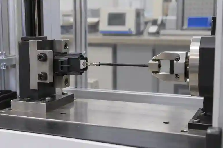
IEC 60512-15-1:2008 defines a standard method for assessing the effectiveness of a contact retaining system against axial load. See IEC 60512-15-1. IEC 60512-13-1:2006 addresses engaging and separating forces for mating connectors, including locking or sealing devices. See IEC 60512-13-1. These methods do not replace the applicable connector product specification, test speed, conditioning or acceptance value.
4. Inspect molded and metal features before changing the tool
On the housing, look for flash at the lead-in or locking shoulder, short shot, burn-related deposits, gate or ejector influence, mismatch, local gloss change, warped cavity walls and TPA interference. On the terminal, inspect orientation keys, locking lance height, burrs, plating damage, crimp-barrel distortion and wire alignment. Use magnified images and retain failed parts in the tested state.
Compare the failure pattern by mold cavity, terminal lot and insertion station. If one terminal lot fails across several mold cavities, changing the mold first may be the wrong experiment. If one mold cavity repeats the same geometric and force pattern with controlled terminals, the mold hypothesis becomes stronger.
5. Verify primary lock, TPA sequence and test setup
The terminal should reach the released seated position before the TPA is applied. Do not force a TPA closed to hide an incompletely seated contact. TE Connectivity notes that a locking lance engages the housing retention shoulder after full insertion and that TPA devices can support proper installation when specified. See TE guidance on applying crimped terminals to plastic housings. Product drawings and application specifications still control the actual sequence and checks.
For force testing, control sample conditioning, pull direction, fixture alignment, jaw position, test speed, zeroing and whether the TPA is fitted. Record the force curve and failure mode, not only the peak value. Distinguish contact pullout, lance deformation, shoulder damage, wire slip, crimp failure and housing fracture.
6. Close T1 with matched dimensional and functional evidence
| Review item | Controlled input | Closing question | Evidence |
|---|---|---|---|
| Cavity geometry | Datum system, fixture and probe path | Does the same cavity pattern repeat after re-setup? | Cavity-indexed dimensional map |
| Terminal condition | Part number, lot, orientation and crimp | Was the contact compliant before insertion? | Incoming and post-test images |
| Primary retention | Lance, molded shoulder and seated depth | Did the lock engage without damage? | Section or optical inspection |
| TPA operation | Released TPA and assembly sequence | Does it close only after full seating? | Recorded assembly check |
| Force verification | Alignment, speed, conditioning and configuration | Does the approved sample plan meet its product requirement? | Force curves, failure modes and retained samples |
This table is an editorial project-control suggestion, not an industry standard. Related capabilities are listed under mold review service and injection molding service. For corrective-action control, see the T1 corrective-action and retest checklist. To review a connector housing, submit the CAD, controlled drawings, housing and terminal part numbers, resin and terminal lots, cavity map, crimp setup, dimensional results, force curves, TPA version and approved acceptance criteria. No fixed cavity tolerance, insertion force, retention force, pull speed, resin setting, correction result, certification or delivery outcome is promised.
Frequently asked questions
Does high terminal insertion force prove the molded cavity is too small?
No. Orientation, terminal burrs, crimp deformation, debris, fixture alignment and lead-in damage can also raise force. Compare controlled terminals and cavity measurements.
Does low retention force prove the housing material is weak?
No. An incompletely seated contact, damaged lance, wrong terminal variant or incorrect test direction can produce the same symptom.
Can the TPA be used to push terminals into position?
Only if the released application specification explicitly defines that action. In general review, confirm primary seating before applying the secondary lock.
Is one passing pull test enough to approve T1?
No. Use the approved sample plan across relevant mold cavities, terminal lots and conditioning states, and review the failure mode as well as the measured force.
What should be supplied for this T1 review?
Provide released CAD and drawings, datum definitions, resin grade, cavity and sample IDs, molding records, terminal and TPA part numbers, terminal lot and crimp setup, cavity measurements, insertion records, force curves, fixture details and approved acceptance criteria.