For product context, see the coffee machine water tank mould page.
A removable coffee machine water tank can look acceptable in free state and still leak after it seats on the appliance valve. The cause may be a warped sealing land, an offset outlet, local sink around ribs, molding variation, a mismatched seal, or an assembly fixture that does not reproduce the real interface. A useful T1 review therefore connects part geometry, molding history, mating-part condition and a repeatable leak test. Record the released part and mold revision, resin grade and lot, cavity, shot sequence, conditioning time, valve and seal revision, assembly method and test setup. This is a generic engineering example, not a customer case or a universal acceptance standard.
1. Define the sealing interface and its datums
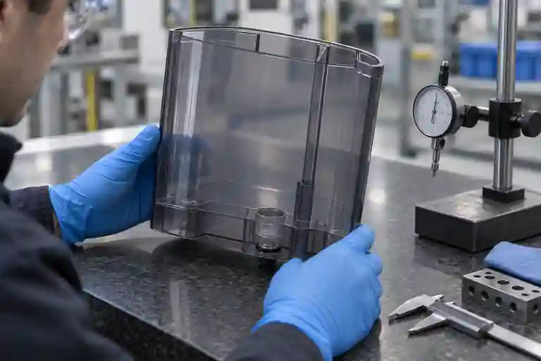
Identify the exact surfaces that locate the tank in the machine and the land that compresses the seal. A valve-seat diameter alone cannot describe the interface if the outlet axis, surrounding base, latch faces and appliance support points are not tied to a datum system. Inspect the tank first in free state and then in a controlled fixture that reproduces the released supports without forcing the part flat.
ISO 5459:2024 defines terminology and rules for datums and datum systems in geometrical product specification. Use a project-approved datum strategy to make free-part and assembled measurements comparable; do not improvise a reference from whichever surface is easiest to reach. See ISO 5459:2024.
2. Separate warpage from local valve-seat geometry
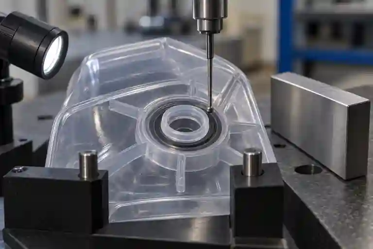
Map the tank base, outlet axis and sealing land as separate characteristics. Global base bow can tilt the valve while a locally flat sealing land remains usable; local ovality, waviness or sink can interrupt seal compression even when the overall tank appears straight. Use the approved contact or optical method, record fixture state and measurement temperature, and retain cavity-linked samples.
ISO 20457:2026 provides a plastics-specific framework for dimensional and geometrical tolerances and acceptance conditions. It emphasizes that material behavior, part design, tool layout and process conditions influence achievable dimensions. Project drawings must still define the functional characteristics and acceptance method. See ISO 20457:2026.
3. Review wall, rib and boss transitions around the outlet
Thick-to-thin transitions, heavy rib roots and concentrated material around an outlet boss can cool and shrink differently from the tank wall. Review the section through the valve seat, rib intersections and nearby corners. Core out unnecessary mass where the design permits, keep transitions gradual and preserve the stiffness needed to resist assembly loading.
Protolabs recommends consistent wall thickness and notes that overly thick bosses can create sink or void risk. Its guidance is useful for DFM review, but it is not a substitute for the released resin data, mold-flow evidence or project validation. See the Protolabs injection molding guide.
4. Connect the defect map to molding evidence
Autodesk describes warpage as deformation caused by internal stresses resulting from shrinkage variation, nonuniform cooling and material-orientation effects. Compare cavity position, cooling layout, gate location, fill and pack history, mold temperatures, ejection condition and part handling. A repeatable direction or cavity pattern is evidence; it is not, by itself, permission to change steel or process settings.
Use a controlled troubleshooting ladder. Preserve a known baseline, change one approved factor at a time, and check the whole part after every trial. A change that improves the valve seat may shift the tank rim, latch, capacity geometry or cosmetic surface. See the Autodesk warpage troubleshooting guidance and material-orientation result guidance.
5. Make the leak test repeatable
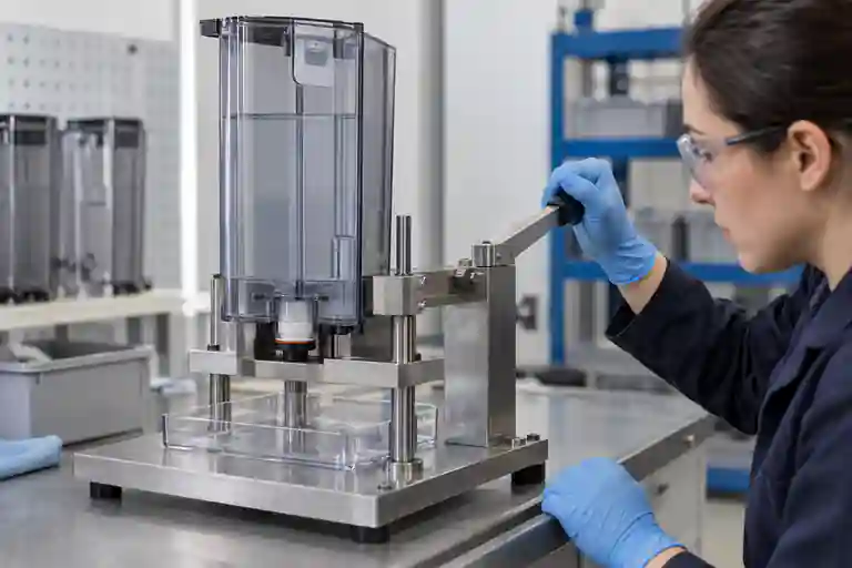
Test the complete controlled interface: tank, valve, seal, supports and the released seating action. Define fill level or pressure, dwell time, conditioning state, water temperature, observation zone and pass/fail method in the project plan. Do not use hand force to make a leaking sample pass, and do not infer a universal test pressure or duration from this article.
Run at least a free-standing check, a controlled seated check and a repeat installation using the same traceable parts. If possible, swap only one known mating component at a time. Record whether leakage starts during seating, dwell, removal or reinstallation, because these patterns lead to different hypotheses.
6. Close T1 with linked evidence
| Review item | Controlled input | Closing question | Evidence |
|---|---|---|---|
| Datum setup | Released supports and reference features | Is free-state geometry measured without forced flattening? | Fixture record and measurement map |
| Valve seat | Outlet axis, sealing land and local base | Is seal compression continuous and repeatable? | Geometry report and section review |
| Molding | Resin, cavity, shot and process version | Does variation follow a cavity or process pattern? | Shot log and retained samples |
| Assembly | Valve, seal and seating action | Does the tank locate without excess force? | Repeat installation record |
| Leakage | Approved test method and observation zone | When and where does leakage begin? | Time-stamped test record |
This table is an editorial project-control suggestion, not an industry standard. Related scope is available in the appliance mould category, mold review service and injection molding service. For corrective-action control, see the T1 corrective-action and retest checklist. To review a specific tank, submit the CAD, controlled drawing, resin specification, valve and seal revisions, test method and traceable trial record. No fixed tolerance, leak pressure, dwell time, molding setting, correction result or delivery outcome is promised.
Frequently asked questions
Can a tank pass dimensional inspection and still leak?
Yes. A report may omit the sealing land, outlet axis, support condition, mating seal or assembled state. The inspection plan must represent the functional interface.
Is visible base warpage always the root cause?
No. Leakage can involve local sealing-land geometry, outlet position, seal condition, valve revision, seating force or contamination. Separate global and local evidence before selecting a correction.
Should the tank be clamped flat during measurement?
Only when the released inspection method defines that state. Otherwise clamping can hide free-state deformation and create a result that the appliance assembly does not reproduce.
Can process adjustment alone solve the problem?
Sometimes, but not automatically. Geometry, wall transitions, cooling, gate position, material behavior, ejection and handling may all contribute. Any change must be validated across the whole part and approved process window.
What should be supplied for a T1 leakage review?
Provide released CAD and drawings, datum and tolerance definitions, resin grade, sample and cavity IDs, process records, conditioning history, valve and seal revisions, assembly method, leak-test procedure, defect photos and approved acceptance criteria.