For product context, see the washing machine tub mould page.
A T1 outer tub can pass a visual check yet show bearing-seat alignment variation, shaft drag, uneven seal contact or water at the shaft-seal interface after assembly. Those symptoms do not identify one cause by themselves. The molded datum structure, bearing-seat geometry, inserted components, bearing installation, shaft runout, seal condition, fixture loading and test method can all affect the result. A useful review preserves the as-tested assembly, separates molded-part geometry from rotating-assembly behavior and then reconnects both to a controlled leak test. Record the released CAD and drawing revision, resin grade and lot, cavity, shot sequence, conditioning state, insert revision, bearing and seal identity, assembly method, fixture and test procedure. This is a generic engineering example, not a customer case or a universal acceptance specification.
1. Define the functional axis and the evidence chain
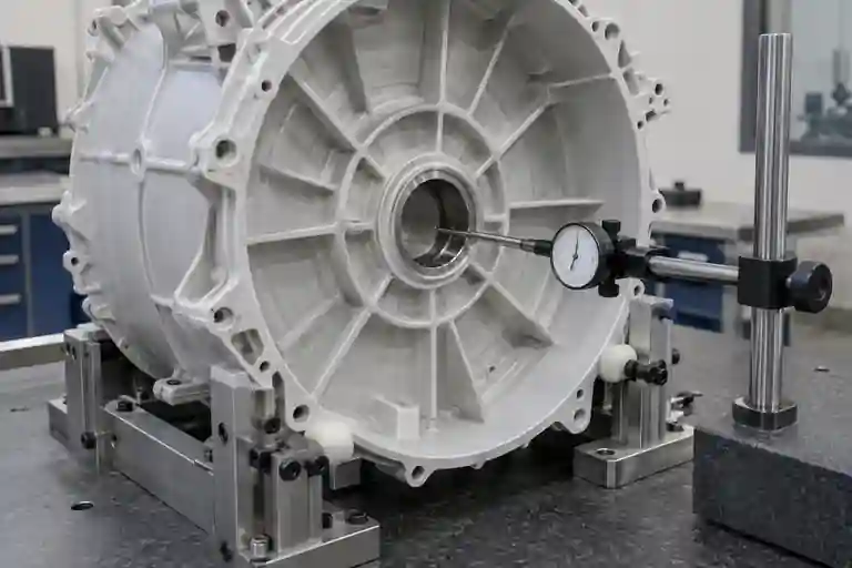
Start with the released product definition. Identify the datums used to establish the tub, the bearing-seat axis, the mating half, the shaft reference and the seal counterface. Do not substitute an easy fixture surface for the functional datum without documented agreement. A bore can appear circular in one section while its axis is displaced or tilted relative to the assembly datum system.
ISO 5459:2024 specifies terminology and rules for datums and datum systems, while ISO 1101:2017 defines the symbol language and interpretation rules for geometrical specifications. See ISO 5459:2024 and ISO 1101:2017. The project drawing and inspection plan must still state the actual datum features, toleranced characteristics, restraint condition and verification method for this tub.
Preserve identity from molded sample to assembled test unit. Record cavity, shot order, measurement setup, bearing installation, seal lot, shaft, fixture and test result under one sample ID. Without that chain, a dimensional map and a leak photograph may describe different conditions.
2. Measure the molded bearing seat before assembly effects are added
Inspect the outer tub in the released free or restrained condition using repeatable supports that do not distort the shell. Measure the bearing-seat size and form only where the drawing requires them, then evaluate axis location or orientation to the released datum system. Record support points, probe strategy, temperature and conditioning state. Remove and replace selected samples to expose setup variation.
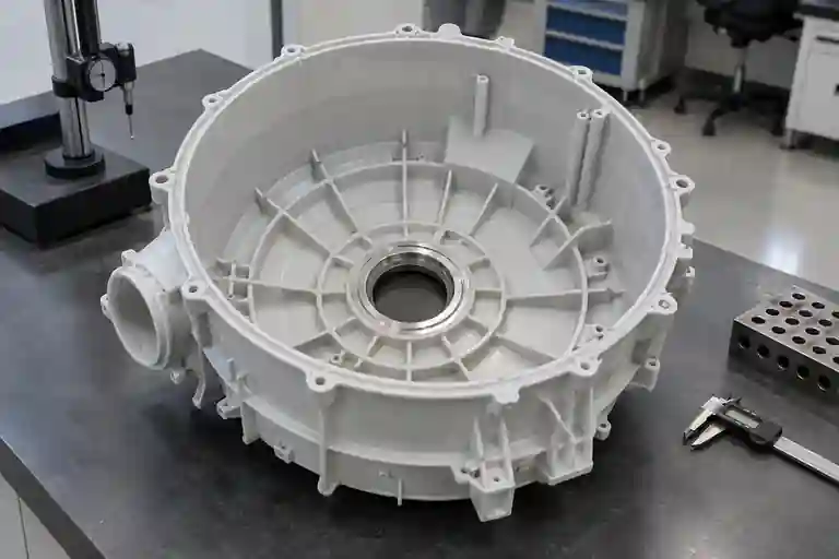
Separate molded features from installed components. If a metal sleeve, bearing carrier or other insert is molded in, record its revision, seating condition and visible interface. If bearings are installed later, retain pre-installation and post-installation results rather than treating them as one geometry. An installation load can change the local seat or reveal a condition that was not visible in a free-state scan.
3. Relate the distortion pattern to molding evidence
ISO 20457:2026 provides a plastics-specific framework for dimensional and geometrical tolerances and acceptance conditions. It recognizes the influence of material behavior, part design, tool layout, processing conditions, nonuniform thickness, cooling and warpage. Functional tolerances must be defined in the product definition data set and checked against achievable molding capability. See ISO 20457:2026.
Compare the direction and cavity pattern of seat-axis change with gate layout, wall transitions, radial ribs, bosses, insert mass, packing history, cooling balance and ejection. Autodesk identifies packing profiles, thickness variation and mold inserts as factors that can influence differential-shrinkage warpage, and advises rerunning the relevant analyses after design or process changes. See Autodesk guidance on differential-shrinkage warpage.
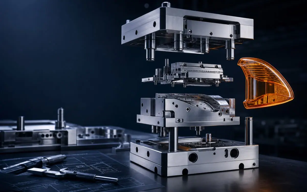
Use simulation and molding trials to test a documented hypothesis. One improved sample does not prove the mechanism if the cavity map, process history and measurement state are not controlled. Recheck filling, packing, cooling, ejection and downstream assembly after any steel or process correction.
4. Separate molded coaxiality from shaft and seal behavior
The molded bearing-seat axis is only one part of the rotating system. Review bearing fit and seating, shaft condition, mating-tub alignment, seal installation, counterface condition and assembly loading. Distinguish shaft-to-bore misalignment from dynamic shaft runout; they are different observations and require different measurements.
SKF explains that shaft-to-bore misalignment and dynamic runout can create uneven radial loading around a radial shaft-seal lip and reduce its ability to follow the shaft. See SKF radial shaft seal guidance. Use the released bearing and seal supplier data for project limits, materials, surface requirements and installation details. This article does not prescribe a universal coaxiality, runout, fit, roughness or seal value.
Inspect the seal and counterface by traceable part and lot. Record twist, damage, contamination, lubricant if approved, insertion depth and tool contact. Do not replace a seal and discard the original before documenting the as-tested condition; a new seal can change the symptom without establishing the cause.
5. Make assembly and leakage testing reproducible
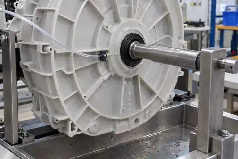
Define the approved mating-half revision, bearings, shaft, seal, insertion tools, fastening sequence, fixture support and conditioning time. Then define the test medium, level or pressure, temperature, orientation, stabilization, observation zone, duration and pass/fail rule in the project procedure. The fixture must support the tub without forcing the bearing seat into alignment or opening the joint.
Use traceable assemblies and change one controlled input at a time. Distinguish a static shaft-seal check from a rotating test and from a complete-appliance cycle. Dry the fixture between tests, verify that water is not migrating from another interface, and retain both passing and failing assemblies for comparison. A wet bearing-seat area is evidence to localize; it is not proof that molded coaxiality is the only cause.
6. Close T1 with linked dimensional, assembly and test evidence
| Review item | Controlled input | Closing question | Evidence |
|---|---|---|---|
| Datum setup | Released features, support and probe strategy | Is the functional axis established reproducibly? | Setup record and repeated measurement |
| Molded bearing seat | Cavity, shot, conditioning and insert state | Does the axis pattern repeat by controlled sample group? | Bore/axis map linked to molding history |
| Rotating assembly | Bearings, shaft, mating half and tools | Was each unit assembled under the same released method? | Assembly traveler and component IDs |
| Seal interface | Seal lot, counterface and installation | Are damage, contamination and seating variation excluded? | Pre- and post-test inspection |
| Leak test | Fixture, medium, orientation and timing | Does leakage repeat without fixture or alternate-path bias? | Approved procedure, zone map and retained unit |
| Corrective action | Versioned hypothesis and single controlled change | Did the change address the verified mechanism without a new defect? | Retest matrix and updated dimensional evidence |
This table is an editorial project-control suggestion, not an industry standard. Related scope is available in the appliance mould category, mold review service and injection molding service. For corrective-action control, see the T1 corrective-action and retest checklist. To review a specific outer tub, submit the released CAD and drawings, resin and cavity records, bearing-seat map, insert and bearing revisions, shaft and seal information, assembly traveler, fixture revision and approved test method. No fixed tolerance, coaxiality, runout, bearing fit, surface finish, seal value, assembly load, test pressure, dwell, acceptance result or delivery outcome is promised.
Frequently asked questions
Does water at the shaft seal prove the molded bearing seat is off-axis?
No. Molded geometry may contribute, but bearing seating, shaft runout, seal installation, counterface condition, mating-part alignment, fixture loading and another water path can also affect the result.
Can the bearing-seat bore be checked without a datum system?
A local size or roundness check is possible, but it does not establish the seat axis relative to the functional assembly. The released datum system and restraint condition are needed for that decision.
Should measurements be taken before or after bearing installation?
Use the states required by the released inspection plan. When installation can influence the seat, record both pre-installation and post-installation results and keep the component and tool identities traceable.
Is replacing the shaft seal enough to close the T1 issue?
Not by itself. A replacement can change the symptom while molded geometry, bearing seating, shaft behavior, contamination or fixture bias remains uncontrolled. Close the issue with repeatable linked evidence.
What should be supplied for a T1 bearing-seat and seal review?
Provide released CAD and drawings, datum definitions, resin and cavity records, molding history, bearing-seat measurements, insert and bearing revisions, shaft runout data if required, seal identity and lot, assembly records, fixture details, defect-zone photographs and approved test criteria.