For product context, see the humidifier water tank mould page.
A humidifier reservoir may pass a visual check and still leak along only one segment of its welded perimeter. The leak can originate in molded-part mismatch, local warpage, interrupted energy-director contact, contamination, fixture support, welding variation or the test setup itself. A useful T1 review separates these layers instead of treating every wet trace as a request for more weld energy. Record the released tank-half and mold revisions, resin grade and lot, cavity, molding history, conditioning state, joint orientation, welding recipe version, horn and fixture identity, assembly sequence and leak-test method. This is a generic engineering example, not a customer case or a universal acceptance standard.
1. Map the leak path and the complete joint boundary
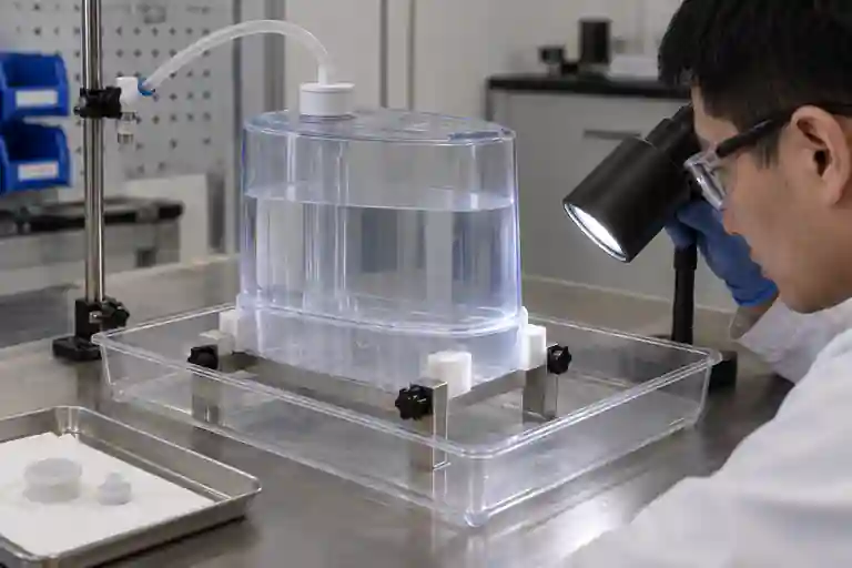
Mark the suspected leak location on a perimeter zone map and retain the tested assembly. Distinguish water that emerges through the weld interface from water that migrates from a cap, valve, tube, threaded insert or handling damage. Use the same fill orientation, observation lighting and dwell sequence for comparison samples. Do not infer a leak path from the final droplet location alone.
Emerson explains that ultrasonic plastic welding transfers vibration through the part, creates frictional heat at the interface, melts the material and forms a weld as it cools. That process description helps define where evidence should be collected, but it does not provide a project recipe. See Emerson Branson ultrasonic plastic welding.
2. Inspect molded geometry before evaluating the weld
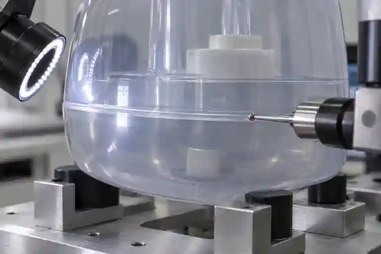
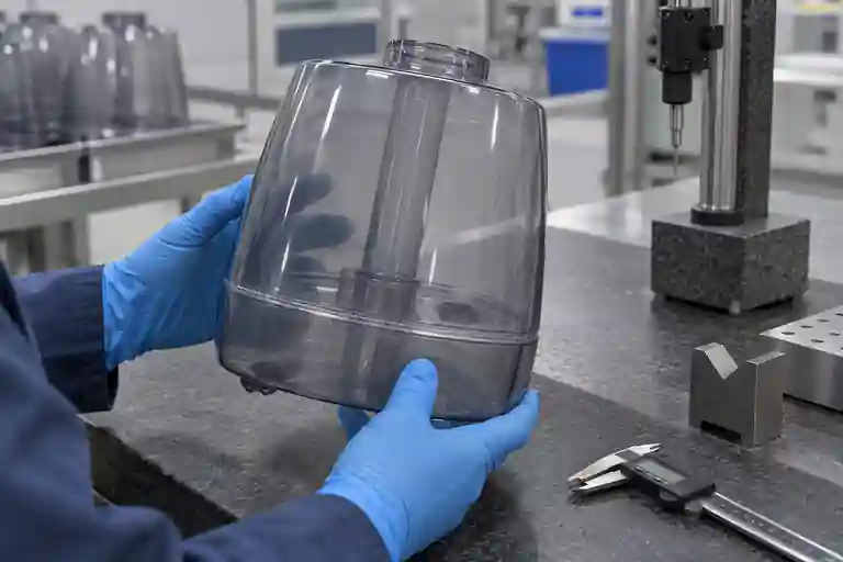
Measure the two tank halves in their approved free or restrained condition before welding. Check joint-plane flatness, perimeter profile, local step, wall transition, energy-director continuity and the locating features that prevent lateral shift. A welded assembly can conceal which half supplied the mismatch, while excessive clamping during inspection can hide the very warpage that interrupts contact.
ISO 20457:2026 provides a plastics-specific framework for dimensional and geometrical tolerances and notes that material, part design, tool layout, processing conditions, nonuniform thickness and cooling can influence molded-part accuracy. Functional tolerances and inspection states still belong in the product definition data set. See ISO 20457:2026.
Autodesk describes warpage as deformation associated with variations in shrinkage and internal stress, including nonuniform cooling and inconsistent process conditions. Use cavity-linked samples and a controlled process record to test that hypothesis rather than adjusting the welder first. See Autodesk warpage troubleshooting.
3. Review joint design, alignment and flash control together
Dukane's ultrasonic plastics assembly guide describes the energy director as a molded feature that concentrates initial contact and melt at the joint. It also notes that the energy director alone does not provide alignment or flash control; those functions must come from part or fixture design. For sealing applications, mating surfaces need controlled flatness and parallelism, and the selected joint concept must suit the resin and functional requirement. See the Dukane Guide to Ultrasonic Plastics Assembly.
Review the released cross-section rather than copying a generic dimension from a guide. Look for interrupted or damaged energy-director segments, resin starvation, bottoming before sufficient collapse, interference that prevents seating, and flash that enters a functional or cosmetic area. Any design change must be evaluated for moldability, alignment, weld formation and the complete tank interface.
4. Lock welding inputs and equipment identity
Capture the approved recipe version and the actual trace for each sample where the equipment supports it. Record horn, booster, converter, actuator, fixture, nest support, maintenance state and part orientation. A parameter name without the corresponding equipment and units is not traceable evidence. Do not compare different machines or tooling sets as if they were one condition.
Emerson's appliance guidance emphasizes choosing the joining technology for the particular appliance geometry and performance need, including reservoirs and demanding seals. This supports a process-neutral review: ultrasonic welding should not be assumed correct merely because it was used in the first trial. See Emerson Branson plastic welding solutions for appliances.
5. Make the leak test reproducible
Define the approved fluid, fill level or pressure, conditioning state, temperature, dwell time, orientation, observation area and pass/fail method. Separate a static reservoir test from an assembled appliance test and from any cyclic or transport condition. The test fixture must support the tank as intended without squeezing the weld closed or opening it artificially.
Repeat installation and testing with traceable parts. If investigating a suspected cause, change only one controlled input at a time: one tank half, one cavity, one fixture, one recipe revision or one test condition. Dry and inspect the assembly between tests so residual water does not create a false recurrence.
6. Close T1 with linked molding, welding and test evidence
| Review item | Controlled input | Closing question | Evidence |
|---|---|---|---|
| Leak map | Tank orientation and observation method | Where does the path begin? | Zone photos and sample ID |
| Molded joint | Cavity, conditioning and inspection state | Is contact continuous before welding? | Perimeter profile and free-state map |
| Joint design | Released section and resin | Are alignment, melt path and flash control defined? | CAD section and revision record |
| Welding | Recipe, horn, fixture and trace | Was each sample produced under a known condition? | Machine record and equipment IDs |
| Leak test | Approved fluid, support and dwell sequence | Is the result repeatable without fixture bias? | Test record and retained assembly |
This table is an editorial project-control suggestion, not an industry standard. Related scope is available in the appliance mould category, mold review service and injection molding service. For corrective-action control, see the T1 corrective-action and retest checklist. To review a specific reservoir, submit the CAD, controlled drawing, resin specification, molded-part maps, weld trace, fixture record and leak-test method. No fixed weld amplitude, force, time, collapse, tolerance, leak pressure, acceptance result or delivery outcome is promised.
Frequently asked questions
Does a leak always mean the ultrasonic energy was too low?
No. A leak can involve molded mismatch, warpage, joint interruption, contamination, alignment, fixture support, equipment state, recipe variation or the test method. Increasing energy without diagnosis can add flash or damage while leaving the cause unresolved.
Can the welded assembly alone identify which tank half is wrong?
Not reliably. Measure and retain both molded halves before welding, with cavity and conditioning records. The weld can pull, restrain or conceal free-state variation.
Is a continuous visual weld line proof of a sealed joint?
No. Appearance is useful evidence but does not replace a project-defined functional leak test. Subsurface voids or a narrow interrupted segment may not be obvious under normal lighting.
Should the fixture force warped halves into contact?
The production fixture may provide approved support and alignment, but it should not be used to hide uncontrolled molded geometry. Free-state and fixture-state evidence should both be retained when they matter to function.
What should be supplied for a T1 weld-leak review?
Provide released CAD and drawings, resin and cavity records, molded-joint measurements, sample IDs, conditioning history, weld equipment and recipe versions, horn and fixture identity, machine traces, leak-test procedure, defect-zone images and approved acceptance criteria.