For product context, see the dishwasher inner tub mould page.
An injection-molded dishwasher inner tub can appear sound while the drain-sump interface leaks after assembly. The wet trace may come from flange warpage, local waviness, groove geometry, gasket damage, contamination, fastener sequence, mating-part mismatch, fixture support or the test method. A useful T1 review separates the molded part, seal system, assembly and test evidence before changing the mold or tightening the joint. Record the released CAD and drawing revision, resin grade and lot, cavity, molding conditions, conditioning state, mating-part revision, gasket identity, assembly sequence, fixture and leak-test method. This is a generic engineering example, not a customer case or a universal acceptance standard.
1. Confirm the leak path and interface boundary
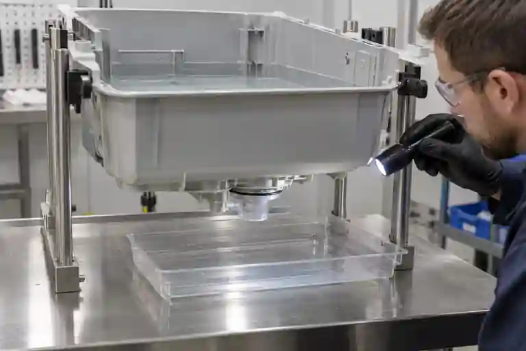
Map the first visible wet location and retain the tested assembly. Distinguish a path through the drain-sump seal from water migrating along a hose, fastener, molded insert, pump interface or handling damage. Use the same tub orientation, water level or approved pressure condition, observation lighting and dwell sequence for comparisons. A droplet beneath the flange is evidence to investigate, not proof of the originating path.
Document the complete stack: molded tub flange, gasket or O-ring, mating sump, retainers, fasteners and any locating features. Photograph the dry interface before assembly and the wetted path after the approved test. Do not disassemble before preserving the as-tested condition.
2. Measure molded geometry in a defined inspection state
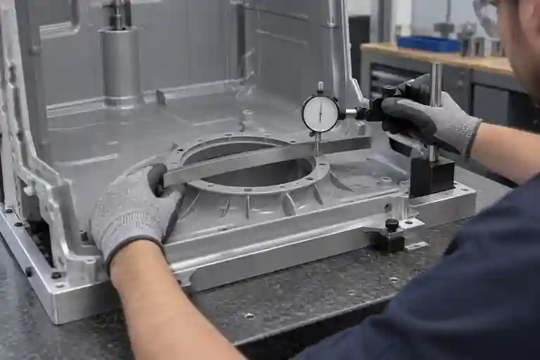
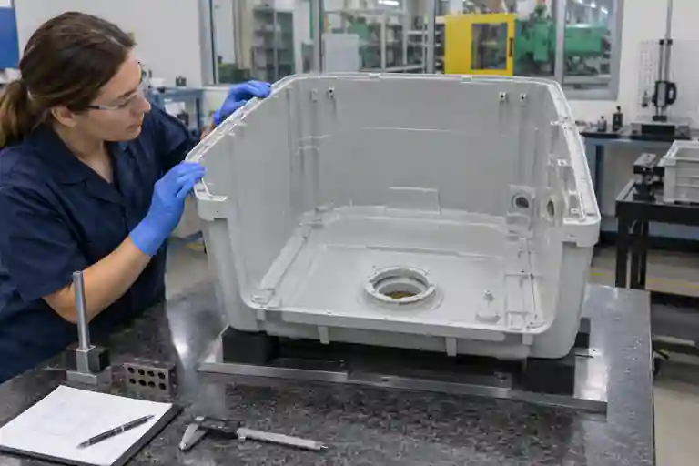
Inspect the released drain-sump flange in the specified free or restrained state. Check datum setup, flange flatness or profile, local high and low zones, groove depth and width where applicable, bolt-boss height, wall transitions and the relationship to the tub support points. Over-clamping during inspection can hide the deformation that changes seal compression during assembly.
ISO 20457:2026 provides a plastics-specific framework for dimensional and geometrical tolerances. It notes that material, part design, tool layout, processing conditions, nonuniform thickness, cooling and warpage influence molded-part accuracy; functional tolerances and inspection conditions belong in the product definition data set. See ISO 20457:2026.
3. Separate warpage causes from seal-system causes
Autodesk describes warpage as deformation associated with variations in shrinkage and internal stress. Its troubleshooting guidance includes nonuniform cooling, inconsistent shrinkage, material variation and process variation among possible contributors. Compare cavity-linked parts, molding records and free-state maps before concluding that the gasket or tightening process is the only cause. See Autodesk warpage troubleshooting.
Review wall-thickness changes, ribs, bosses, gate relationship and cooling around the drain opening. A correction should address the verified mechanism and then be rechecked for filling, packing, ejection, assembly and sealing. One local steel change can move deformation elsewhere.
4. Review the released seal housing and seal condition
If the released design uses an O-ring, housing dimensions, mating surfaces and the selected seal must be reviewed as one system. ISO 3601-2:2025 specifies housing dimensions for defined O-ring applications and notes that special applications require agreement between the seal manufacturer and user. It should guide a project review, not be copied blindly into a dishwasher design. See ISO 3601-2:2025.
The Parker O-Ring Handbook covers static-seal fundamentals, gland design and sealing-surface considerations. Use the released gasket supplier data and the actual application environment to define the project values; this article does not prescribe squeeze, gland depth, fill or surface finish. See the Parker O-Ring Handbook.
Inspect the seal by traceable lot and part number. ISO 3601-3:2005 defines quality acceptance criteria and surface-imperfection classifications for standardized O-rings. If the dishwasher uses another gasket type, apply its released specification instead. See ISO 3601-3:2005.
5. Make assembly and leak testing reproducible
Define the approved mating-part revision, gasket installation method, lubricant if allowed, fastener sequence, tightening tool, fixture support and conditioning time. Then define the test fluid, level or pressure, temperature, dwell, orientation, observation zone and pass/fail rule. A fixture must support the tub as intended without flattening the flange or opening the joint.
Use traceable assemblies and change one controlled input at a time. Dry the tub and fixture between tests, and separate a static component test from a complete-appliance test and any cyclic condition. Record both passing and failing samples so the evidence does not become a collection of isolated defect photographs.
6. Close T1 with linked molding, seal and test evidence
| Review item | Controlled input | Closing question | Evidence |
|---|---|---|---|
| Leak path | Orientation and observation method | Where does water first cross the boundary? | Zone map, photos and sample ID |
| Molded flange | Datum, cavity and inspection state | Is the released sealing geometry repeatable? | Profile or flatness map and molding record |
| Seal housing | Released groove and mating part | Does the complete stack match the approved design? | CAD section and revision record |
| Seal condition | Part number, lot and installation | Is damage, twist or contamination excluded? | Incoming and post-test inspection |
| Assembly | Fixture, sequence and tool identity | Was each sample assembled under known conditions? | Assembly traveler and tool record |
| Leak test | Approved fluid, support and dwell | Is the result repeatable without fixture bias? | Test procedure and retained assembly |
This table is an editorial project-control suggestion, not an industry standard. Related scope is available in the appliance mould category, mold review service and injection molding service. For corrective-action control, see the T1 corrective-action and retest checklist. To review a specific tub, submit the CAD, controlled drawing, resin and cavity records, flange map, seal specification, assembly record and leak-test method. No fixed tolerance, seal squeeze, gland dimension, surface finish, tightening value, leak pressure, dwell, acceptance result or delivery outcome is promised.
Frequently asked questions
Does a drain-area leak prove the molded flange is warped?
No. It can also involve the seal, mating sump, contamination, fastener sequence, assembly support, another fluid path or the test method. Preserve the complete as-tested assembly before assigning the cause.
Should flange flatness be measured with the tub clamped down?
Only in the inspection state defined by the released drawing or test plan. Record free-state and restrained-state results when both affect function; uncontrolled clamping can hide the deformation under review.
Can a generic O-ring table define the dishwasher seal groove?
Not by itself. The project must consider the released seal, housing, mating part, material compatibility, environment and supplier guidance. Special applications require project-specific agreement.
Is a new gasket enough to close the T1 issue?
Not unless the cause and repeatability are demonstrated. A replacement gasket may temporarily change the result while leaving flange geometry, assembly variation or contamination uncontrolled.
What should be supplied for a T1 drain-seal review?
Provide released CAD and drawings, resin and cavity records, molding history, flange measurements, mating-part revision, seal part number and lot, assembly sequence and tool record, test procedure, defect-zone photographs and approved acceptance criteria.