For the related product context, see the refrigerator drawer mould page.
When an injection-molded refrigerator drawer feels smooth by itself but sticks, tilts or changes resistance inside the appliance at T1, the symptom does not identify one cause. Drawer-body warpage, rail-profile deviation, left-to-right twist, cabinet-guide position, assembly restraint, load placement, surface damage, contamination and the test path can all change the result. A useful review separates the free molded part from the mating system and then reconnects them through a controlled sliding test. Record the exact drawer, cabinet and guide revisions; resin grade and lot; mold cavity and shot sequence; conditioning interval; datum and support method; mating-part identity; load condition; fixture version; pull direction; and test procedure. This is a generic engineering example, not a customer case or a universal refrigerator-drawer specification.
1. Freeze the assembly stack and sample identity
Define the complete sliding system before measurement: drawer body, molded side rails or runners, front and rear walls, cabinet guides, stops, rollers or inserts if present, attachment points, and any production load. A different cabinet guide, drawer revision or assembly position can create a result that resembles molded rail warpage.
Link every drawer to mold revision, cavity, resin lot and shot order. Link every mating guide and fixture to a controlled revision. Photograph the free-state part before installation and preserve any contact marks after the sliding test. This makes it possible to distinguish as-molded geometry, handling damage and assembly-generated contact.
2. Establish functional datums and a non-forcing support
The inspection plan should select datums that represent how the drawer is located and guided in the appliance. ISO 5459:2024 specifies terminology, rules and methodology for datums and datum systems. See ISO 5459:2024. The standard does not select the functional datum scheme for a particular drawer; the released product-definition data and inspection plan must do that.
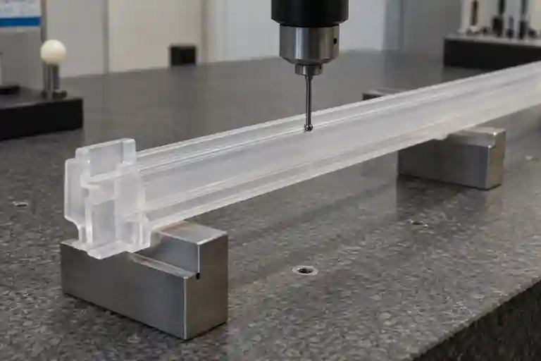
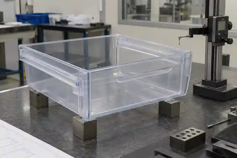
Support the drawer in a repeatable way that does not force the base, walls or rails into the expected shape. Record support points, restraint condition, orientation, probe path and temperature. Remove and replace the same sample, then repeat the setup before comparing cavities. If the result moves with the fixture, the setup contribution must be resolved before a tool correction is selected.
3. Map rail profile, bow, twist and stop features separately
Inspect each rail or runner for the drawing-defined profile, straightness, location, local thickness, edge condition, parting-line mismatch, flash, sink-related distortion and damage. Compare left and right rails to the same functional datum system. Also review the base and side walls because a rail can be locally correct while the drawer body twists its assembled path.
ISO 1101:2017 defines the symbol language and interpretation rules for geometrical specifications. See ISO 1101:2017. It does not provide a universal rail straightness, profile or parallelism value. The design authority must define the controlled feature, tolerance zone, datum relationship, restraint state and acceptance method for this assembly.
Record where contact first appears during insertion, mid-travel and near the stop. A high spot, a bowed rail, a twisted body and an offset stop can all produce different signatures. Do not reduce the review to one overall width measurement.
4. Separate free-state geometry from cabinet and load effects
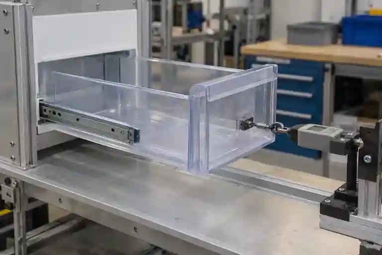
Measure the drawer in the approved free-state condition first. Then evaluate it in the released cabinet or a correlated fixture with controlled mating guides. Keep unloaded, distributed-load and project-specific load states separate. Load can change wall spread, base sag and rail engagement; fixture stiffness or guide spacing can either hide or exaggerate a molded deviation.
Use one controlled variable change at a time. Swap the drawer while holding the cabinet and guides constant, then swap the mating guide or cabinet while holding the drawer constant. Check whether resistance changes at the same travel position and whether witness marks agree with that location. This does not automatically prove root cause, but it prevents a broad mold correction from being based on a mixed assembly condition.
ISO 291:2008 sets specifications for conditioning and testing plastics under constant atmospheric conditions. See ISO 291:2008. It does not define the conditioning state for every refrigerator drawer application. The material specification and released test plan must identify the relevant conditioning, storage and test sequence.
5. Connect the deformation pattern to molding evidence
Compare dimensional and sliding results by cavity, shot sequence and conditioning interval. Review gate location, wall-thickness transitions, corner geometry, ribs, base-to-wall junctions, rail sections, cooling layout and ejection direction against the observed bow or twist pattern. Retain material preparation, fill and pack records, mold-temperature and cooling evidence, part weight and ejection observations.
ISO 20457:2026 provides a plastics-specific framework for dimensional and geometrical tolerances and acceptance conditions, recognizing material, shrinkage, warpage, geometry and processing influences. See ISO 20457:2026. Autodesk explains that warpage can arise from variations in shrinkage, differential cooling and orientation effects. See Autodesk guidance on shrinkage prediction and warpage. These references support hypothesis testing; they do not prove that one process input caused a particular drawer result without matched production evidence.
6. Close T1 with matched dimensional and sliding evidence
Run the approved functional test with a controlled drawer, mating guide or cabinet, load state, travel path, speed, direction and number of cycles. If the project uses force measurement, preserve the full force-versus-travel trace, starting condition and contact observations rather than only one peak. Repeat after re-fixturing so setup variation is visible.
| Review item | Controlled input | Closing question | Evidence |
|---|---|---|---|
| Free-state setup | Datum system, supports and restraint | Does the geometry repeat after re-fixturing? | Repeated map by cavity and sample |
| Rail profile | Probe path and feature definition | Where do profile, bow or local edge conditions change? | Rail trace and visual record |
| Drawer body | Base, walls and left-to-right relationship | Is the rail path being shifted by body twist? | Cross-section and body-shape comparison |
| Mating system | Cabinet, guides, stops and load state | Which controlled change moves the resistance signature? | Swap matrix and witness marks |
| Functional retest | Travel path, direction and procedure | Does the approved sample plan pass without new damage? | Force trace, failure mode and retained samples |
This table is an editorial project-control suggestion, not an industry standard. Related capabilities are listed under mold review service and injection molding service. For corrective-action control, see the T1 corrective-action and retest checklist. To review a specific drawer, submit the released CAD and drawings, datum definitions, resin and cavity map, mating-guide revision, conditioning record, dimensional results, load state and approved sliding-test criteria. No fixed rail tolerance, profile, guide clearance, conditioning time, sliding force, load, cycle count, process setting, correction result or delivery outcome is promised.
Frequently asked questions
Does a sticking drawer prove that the molded rails are warped?
No. Molded rail geometry can contribute, but cabinet-guide position, body twist, load, surface damage, contamination, stops and the test fixture can create the same symptom.
Should the drawer be measured while clamped flat?
Only if the released inspection plan defines that restraint. Free-state and restrained measurements answer different questions and should be identified separately.
Is overall drawer width enough to approve the rail path?
No. Overall width does not independently describe local rail profile, bow, twist, stop position or the relationship between the two sides.
Can one smooth sliding cycle approve T1?
No. Confirm repeatability across the approved sample plan, relevant cavities, conditioning states, mating components and load conditions, and inspect for new contact damage.
What should be supplied for this T1 review?
Provide released CAD and drawings, datum and restraint definitions, resin grade, cavity and sample IDs, molding records, conditioning history, mating-guide and cabinet revisions, rail measurements, contact observations, load state, sliding traces, fixture details and approved acceptance criteria.