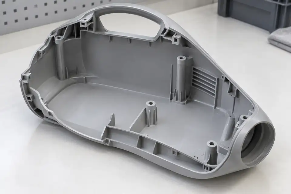
Screw bosses and ribs inside a vacuum cleaner housing change the local section of the shell. If the corresponding outside surface shows a depression, review the boss root, hole bottom, and rib intersection together. An open top does not diagnose a sink mark, and a photograph does not prove the cause. Match inner and outer surfaces on the same section, then record material, process, assembly, and validation questions. This article covers a generic thermoplastic injection-molded housing; it does not assume ABS, PC, or PC/ABS and gives no universal ratio or machine-setting recipe.
1. Match the outside depression to the inside boss
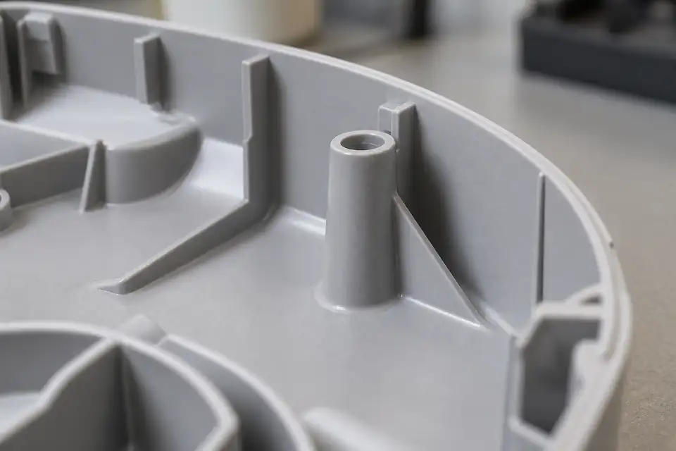
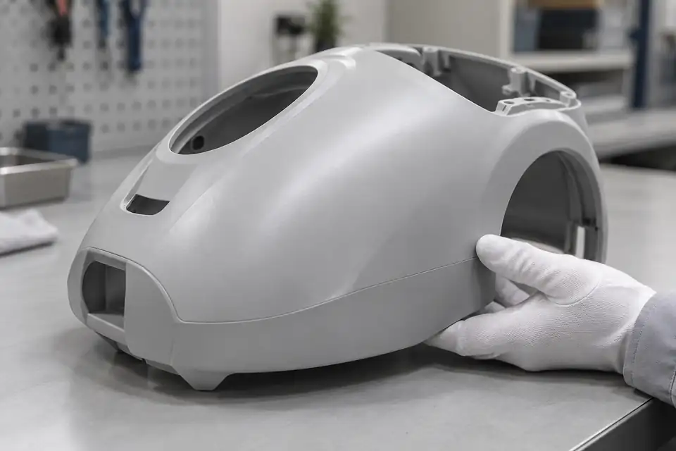
On the current 3D/2D model, mark the controlled cosmetic area, boss locations, ribs, and the corresponding outside surface on one section. General design guidance identifies local thick regions, boss/rib junctions, and the opposite surface as places worth reviewing for sink-mark risk. Here, “sink mark” describes a surface observation; it is not whole-part scale shrinkage and does not establish that every depression has the same cause.
If a sample exists, record whether the depression is present before assembly. That helps separate observation timing, but deformation from tightening a screw or assembly loading is not automatically injection shrinkage. Keep the project resin grade, fillers or modifications, color, and surface requirements explicit. See the pre-mold DFM review checklist for general inputs and the vacuum cleaner housing mold page for product context.
2. Inspect the boss root and hole bottom, not only the open top
Put at least three sections into the review: the boss-to-shell connection, the path from hole bottom to cosmetic surface, and the boss intersection with a rib or neighboring wall. An opening at the top does not prove that the root has no thick region. Hole depth, bottom shape, and shell curvature must come from the current model, not an online dimension.
“Core out” here means a part-geometry direction for reducing excess material; it is not an instruction to drill through the cosmetic surface. Check surface continuity, the screw interface, locating or mating functions, draft, and mold implementation together. If the section or material information is incomplete, record it as pending rather than treating a deeper hole or thinner boss as a universal answer.
3. If a rib supports the function, recheck the junction
When a boss must connect to a wall or retain assembly support, compare a rib connection, local material relief, and the original solid transition as candidate geometries. A rib can avoid a bulky connection, but the combined section at the rib root, boss root, fillet, and side wall still needs review. More ribs, thinner ribs, or larger fillets are not automatically better without the function and manufacturing constraints.
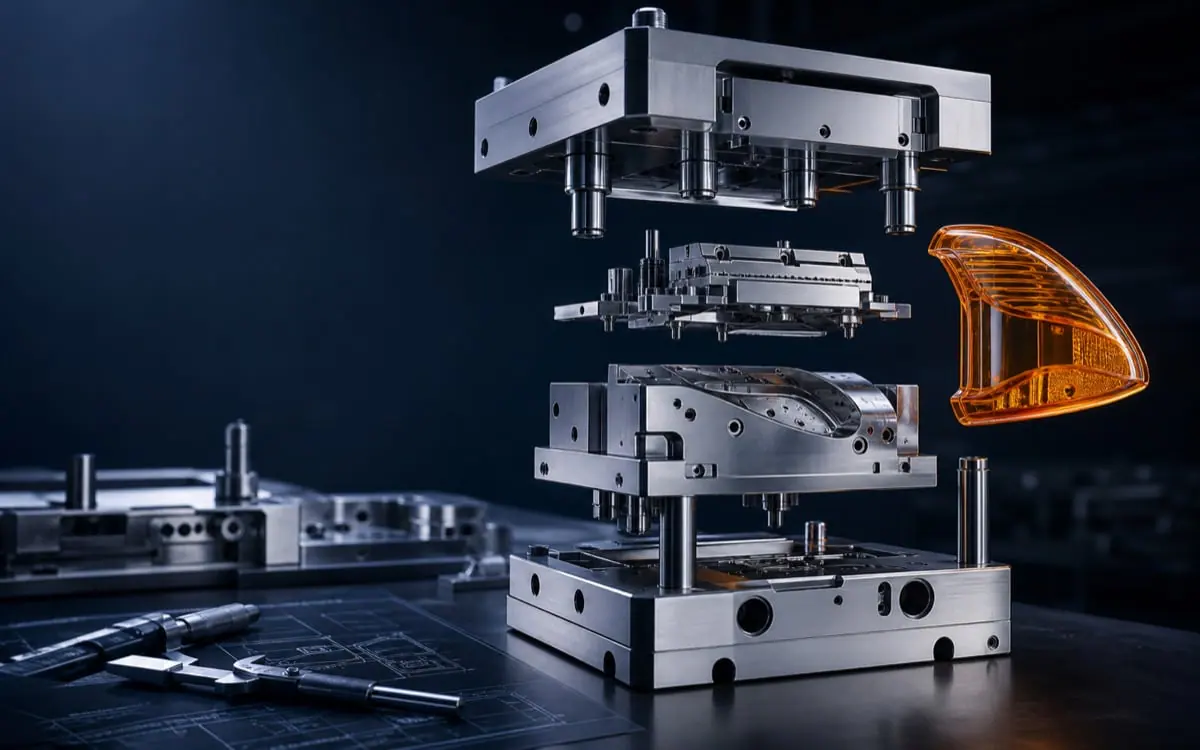
Mark original and candidate geometry side by side, including changes to the screw interface, neighboring clearance, locating features, and draft. A fillet must balance stress concentration and local material accumulation; it should not be removed everywhere or enlarged without limit. For implementation context, see mold design and manufacturing services.
| Review item | Existing section | Candidate change | Function to retain | Risk to validate |
|---|---|---|---|---|
| Boss root / hole bottom | To be supplied | To compare | Screw interface and cosmetic boundary | Local thick region, assembly deformation |
| Rib root / wall junction | To be supplied | To compare | Support, locating, draft | Material accumulation, mating conflict |
4. Separate geometry, material, and process questions
Sink-related appearance is affected by geometry, material, mold, and process. Without the current process record, do not claim that more packing pressure must solve it, and do not claim that process adjustment is irrelevant. This article gives no temperature, pressure, time, shrinkage-rate, or other fixed recipe; the project engineer must define conditions from the resin grade, machine, mold, and validation plan.
Record non-changeable cosmetic surfaces, specified material, color, and texture separately. Texture may change visibility, but it does not prove that the local structure is sound. A color change or deeper texture is not permission to relax acceptance requirements. For sample and process validation context, see molding and injection services.
5. Turn the review into cosmetic and assembly checks
For each boss, record the controlled surface, existing section, candidate change, required connection or mating function, cosmetic observation conditions, and assembly validation item. Cosmetic evaluation should use the project’s specified color, surface state, viewing condition, and acceptance basis. Connection, durability, or screw-related methods must be confirmed by the product owner. A better-looking surface does not prove boss function, production stability, or overall part quality.
When the project has not defined a requirement, leave it pending; do not invent sample counts, torque, life, depth, or acceptance thresholds. Provide the current housing drawing, boss section, material, and cosmetic/assembly requirements through submit the housing drawing and boss question, with appliance molds as related reading. This article does not promise zero sink marks, a fixed lead time, specific equipment, or certification.
Frequently asked questions
Why can the cosmetic surface show a sink mark when the boss top is open?
An opening at the top does not prove that the boss root is no longer thick. Review the hole-bottom path, boss-to-shell connection, and material, mold, and process conditions. The actual defect still requires project evidence.
Is a thinner boss or rib always better?
No. Material relief must preserve connection, locating, or support functions while also passing draft, fit, and manufacturing review. Do not remove necessary structure for appearance alone.
Can an online boss-wall or rib-thickness ratio be the acceptance standard?
No. A general design suggestion cannot replace this project’s material, geometry, function, and validation conditions. This article gives no universal ratio or pass line.
Will increasing packing pressure eliminate a sink mark at the boss?
It is not guaranteed. Geometry, material, mold, and process interact; without project inputs and evidence, a single machine adjustment is not a universal solution.
If texture or color makes the mark less visible, is the issue solved?
Not automatically. Visibility, local structure, and assembly function are separate judgments. Confirm them against agreed cosmetic and functional requirements rather than changing material, color, or acceptance criteria on assumption.