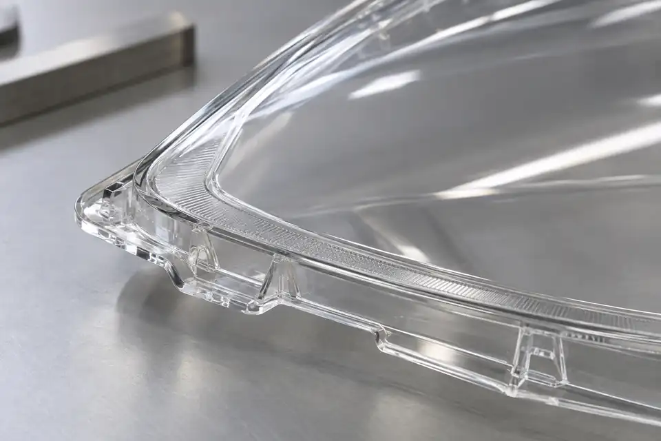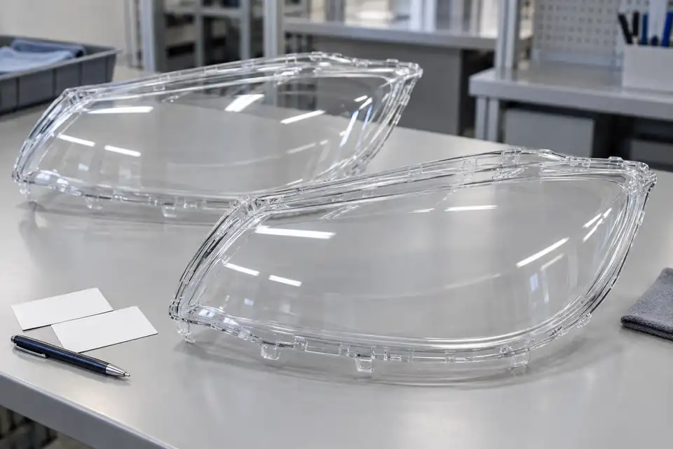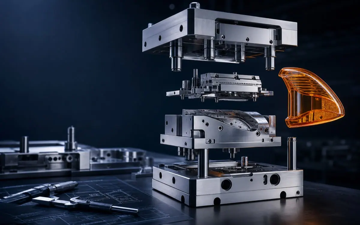
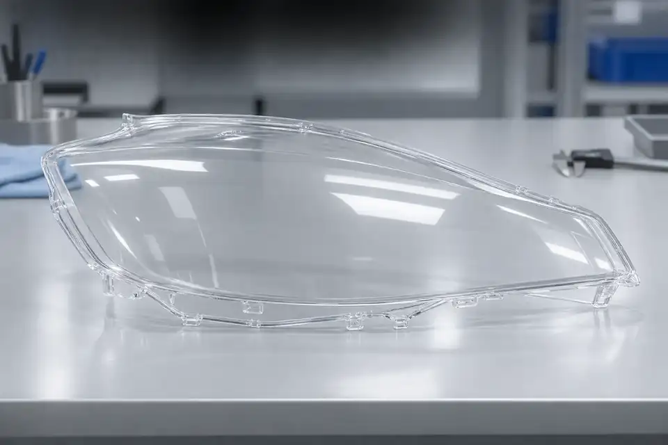
Hiding a gate vestige at the edge does not prove that a weld line avoids a controlled area. On a PC automotive headlamp outer lens cover, gate location changes the filling route and therefore where different flow fronts may meet. Review the visible or optical control zones and the mounting or mating boundaries first, then compare candidate gating concepts and record molded-in-stress risks for later validation. This article concerns a PC transparent outer lens cover—not a thick internal collimating or projection lens and not a PC/ABS lamp housing. Simulation can support a comparison; it cannot replace physical appearance, strength, or optical acceptance.
1. Mark controlled zones on the same drawing revision
Prepare the current 3D/2D revision, the project-specified PC material information, the visible or optical/appearance-controlled zones, mounting or sealing interfaces, and locations where a gate vestige is permitted. Do not automatically treat an edge as low risk: it may still affect assembly, appearance, or a later process.
“Where the gate cannot go” and “where a weld line cannot appear” are different questions. A gate vestige remains after the gate separates from the part; a weld line relates to meeting flow fronts. Mark both constraints before comparing concepts. Use the automotive headlamp mould and lamp lens mould pages for product context and the pre-tooling DFM review checklist for shared inputs.
2. Follow the filling route, not only the gate mark
For each candidate gate, follow the expected filling sequence: where could flow split, where could it meet again, would that meeting enter a visible or mechanically controlled zone, and do venting or mold-mechanism constraints need engineering review? Multiple gates create meeting-front questions; a single gate does not guarantee no weld line because holes, obstacles, or splits in the actual geometry can make fronts meet again. Do not assume every cover has the same holes or obstacles or draw a definite meeting location without the project geometry.
If no analysis has been run for the current geometry, material, and boundary conditions, label the item “to be analyzed.” Do not turn a sketch, a default software recommendation, or a found color plot into a measured result. Weld-line prediction is also affected by analysis conditions such as the model and mesh. It is useful for framing questions and comparing candidates, not for declaring a physical defect absent.
3. Compare gates with the same inputs
| Review item | Concept A (project input) | Concept B (project input) | Evidence to confirm |
|---|---|---|---|
| Permitted gate zone and vestige treatment | [fill] | [fill] | drawing mark, appearance requirement |
| Gate location, count, and section | [fill] | [fill] | design rationale |
| Expected filling route and meeting zone | [fill] | [fill] | analysis basis or open item |
| Conflict with controlled and mating surfaces | [fill] | [fill] | risk review |
| Venting, packing, and later validation | [fill] | [fill] | engineering confirmation and plan |
Do not rank concepts by gate name alone. Fan, edge, or valve gates only become comparable with the actual geometry, material, vestige requirement, and tooling constraints. A larger gate or more gates is not automatically better, and a single gate is not a zero-weld-line promise. If inputs are missing, keep the comparison open instead of inventing a universal winner.
4. Check molded-in stress when improving the line
Reducing line visibility may also change filling, packing, shear, and cooling conditions. PC outer covers additionally require attention to molded-in stress and the possibility of cracking during a later coating process. Molded-in stress is not the weld line itself; record and validate them separately. Do not extract one heating, speed, or packing action from a material note and present it as a universal PC-cover recipe. Conditions depend on grade, geometry, equipment, and project requirements.
Keep appearance, filling/packing, assembly, and stress-related validation questions in one review record. Polarized-light observation may be a project-selected way to observe stress, but without an actual test and criterion it cannot support a passing claim, and it cannot prove that a supplier has a particular instrument or capability.
5. Turn the review into verifiable next steps
Leave a record of the selected or pending gate location and rationale, controlled zones and material revision, prediction basis and limits, risks requiring validation, and unresolved tooling conflicts. A software gate recommendation must still be checked against appearance, structure, venting, and manufacturability. A model that does not display a weld line does not prove that the physical part has none.
Later, review the controlled surfaces, appearance, assembly behavior, and relevant stress risks under the project’s agreed sample conditions and inspection method. That is engineering validation, not a universal threshold created by this article. For the later closure workflow, see the T1 corrective-action and retest checklist; the validation entry point is the trial and injection molding service.
FAQ
If the gate is placed at the edge, will the weld line avoid the visible area?
Not necessarily. Follow splitting and meeting locations and compare them with the controlled area for the current revision. A gate vestige and a weld line are different features.
Does one gate guarantee no weld line on a PC cover?
No. Actual geometry can split flow and make fronts meet again. Do not assume every cover has the same holes or obstacles.
Must a PC outer cover use a fan gate or valve gate?
There is no context-free answer. Compare concepts against material, geometry, vestige requirements, and tooling constraints.
Can higher temperature, speed, or packing pressure solve the weld line?
Not as a universal instruction. Any improvement must be checked against molded-in stress, appearance, assembly, and later operations.
If simulation shows no weld line, can appearance or production be approved?
No. Predictions depend on model and mesh conditions, and a recommended location does not prove physical appearance acceptance or manufacturability.
Submit drawings and gate questions
Prepare the current cover drawing, specified PC material information, controlled-zone marks, permitted vestige locations, and candidate gates through submit headlamp cover drawings and gate questions. This article does not promise zero weld lines, zero stress, optical or regulatory acceptance, a fixed mold life, or a delivery date.